SC743 Chassis Manual
6. and 7. Sideband Headers
The sideband headers are designated JP51 and JP52. For
Sideband Headers
Pin # | Definition | Pin # | Definition |
2 | Mobile rack |
| Controller |
1 | |||
| Addressing |
| ID (SB6) |
| (SB5) |
|
|
4 | Reset (SB4) |
| GND (SB2) |
3 | |||
6 | GND (SB3) |
| SDA (SB1) |
5 | |||
8 | Mobile rack |
| SCL (SB0) |
7 | |||
| ID (SB7) |
|
|
10 | No Connec- |
| No Connec- |
9 | |||
| tion |
| tion |
|
|
|
|
8. Upgrade Connector
The upgrade connector, designated JP46, is used for diagnostic purposes only. This connector should only be used by a certified and experienced technician.
9. Activity LED Header
The activity LED header, designated JP26, is used to indicate the activity status of each SAS drive. For the activity LED header to work properly, connect a
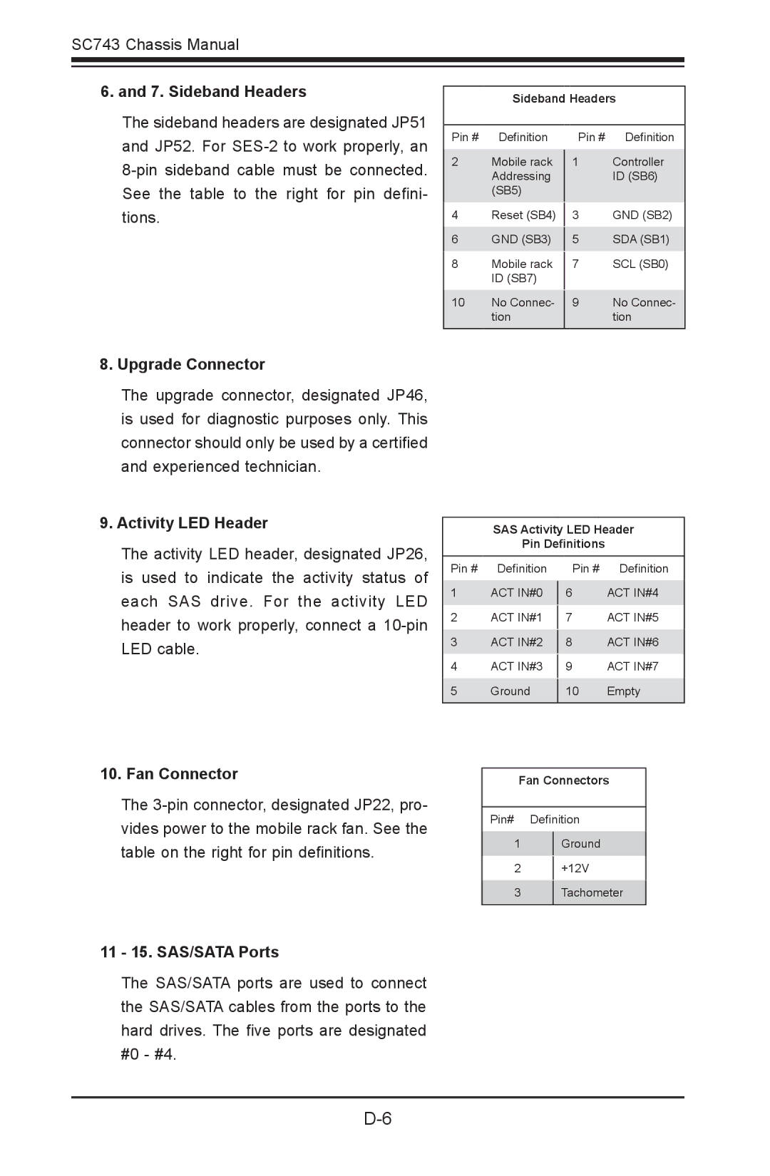
10. Fan Connector
The
11 - 15. SAS/SATA Ports
The SAS/SATA ports are used to connect the SAS/SATA cables from the ports to the hard drives. The five ports are designated #0 - #4.
SAS Activity LED Header
Pin Definitions
Pin # | Definition | Pin # | Definition |
1 | ACT IN#0 |
| ACT IN#4 |
6 | |||
2 | ACT IN#1 |
| ACT IN#5 |
7 | |||
3 | ACT IN#2 |
| ACT IN#6 |
8 | |||
4 | ACT IN#3 |
| ACT IN#7 |
9 | |||
5 | Ground |
| Empty |
10 | |||
|
|
|
|
Fan Connectors
Pin# Definition
1Ground
2+12V
3Tachometer