Appendix D: M35TQ Mobile Rack Specifications
D-9 Front Jumper Locations and Pin Definitions
S UPER R SASM35TQ 1 REV 1.0
JP62
JP38
JP29
JP37 | JP36 | JP50 |
| ||
JP41 | JP40 | ||||
|
| ||||
|
| JP33 |
|
| |
|
| JP43 | JP61 |
| |
JP34 |
JP42 |
JP18
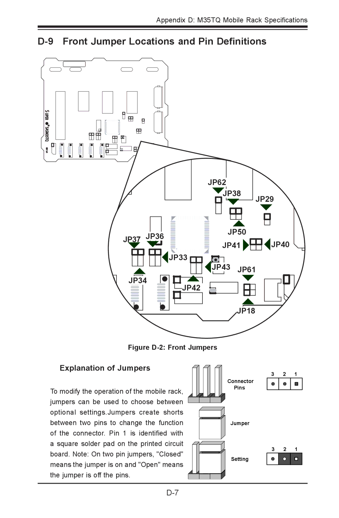
Figure D-2: Front Jumpers
Explanation of Jumpers
To modify the operation of the mobile rack, jumpers can be used to choose between optional settings.Jumpers create shorts between two pins to change the function of the connector. Pin 1 is identified with a square solder pad on the printed circuit board. Note: On two pin jumpers, "Closed" means the jumper is on and "Open" means the jumper is off the pins.
3 2 1 Connector ![]()
Pins
Jumper
3 2 1
Setting