Appendix F:
F-7 Front Jumper Locations and Pin Definitions
SUPER | R |
|
| JP25 |
| SATA743 | REV 3.00 | pb |
JP25
49 |
|
64 | 16 |
1 | H3 |
OH LED
JP18: BUZZER RESET
JP35: GEM24 RST
JP25: OH TEMP.
OPEN 45 C
JP18 MM2
75H
|
|
|
|
| BZ1 |
|
| #7 | #5 | #3 | #1 |
JP10 | JP13 | ACT IN |
|
|
|
+12V GND GND +5V | +12V GND GND | +5V |
|
|
|
|
| #6 | #4 | #2 | #0 |
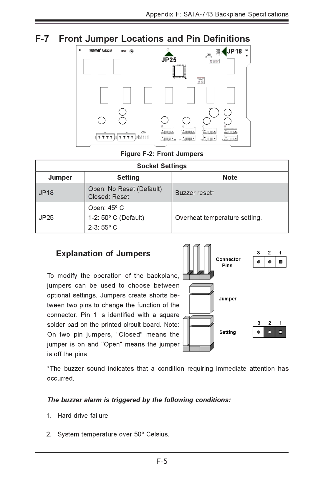
Figure F-2: Front Jumpers
Socket Settings
Jumper
JP18
JP25
Setting
Open: No Reset (Default)
Closed: Reset
Open: 45º C
Note
Buzzer reset*
Overheat temperature setting.
Explanation of Jumpers
To modify the operation of the backplane, ![]()
![]()
![]()
![]() jumpers can be used to choose between
jumpers can be used to choose between ![]() optional settings. Jumpers create shorts be-
optional settings. Jumpers create shorts be- ![]() tween two pins to change the function of the connector. Pin 1 is identified with a square
tween two pins to change the function of the connector. Pin 1 is identified with a square
solder pad on the printed circuit board. Note: On two pin jumpers, "Closed" means the
jumper is on and "Open" means the jumper ![]()
![]() is off the pins.
is off the pins.
Connector
Pins
Jumper
Setting
3 2 1
3 2 1
*The buzzer sound indicates that a condition requiring immediate attention has occurred.
The buzzer alarm is triggered by the following conditions:
1.Hard drive failure
2.System temperature over 50º Celsius.