SC743 Chassis Manual
E-6 Front Connector and Pin Definitions
#1. and 2. JTAG Connector and Upgrade Connectors
The JTAG and upgrade connectors, desig- nated JP47 and JP46, are used for diag- nostic purposes. These connectors should be used by a certified and experienced technician.
#3. MG9072 Chip
The MG9072 is an enclosure management chip that supports the
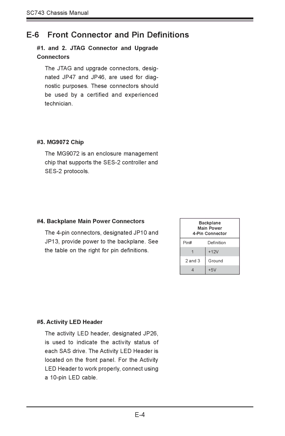
#4. Backplane Main Power Connectors
The
#5. Activity LED Header
Backplane
Main Power
Pin# Definition
1+12V
2 and 3 | Ground |
|
|
4+5V
The activity LED header, designated JP26, is used to indicate the activity status of each SAS drive. The Activity LED Header is located on the front panel. For the Activity LED Header to work properly, connect using a