Appendix E:
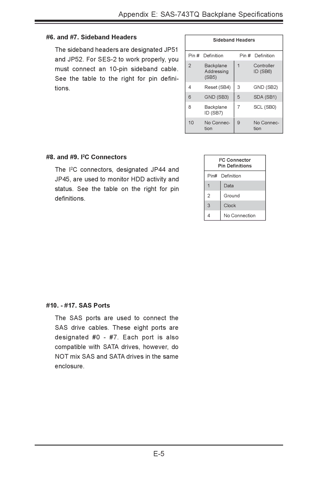
#6. and #7. Sideband Headers
The sideband headers are designated JP51 and JP52. For
Sideband Headers
Pin # | Definition | Pin # | Definition |
2 | Backplane |
| Controller |
1 | |||
| Addressing |
| ID (SB6) |
| (SB5) |
|
|
4 | Reset (SB4) |
| GND (SB2) |
3 | |||
6 | GND (SB3) |
| SDA (SB1) |
5 | |||
8 | Backplane |
| SCL (SB0) |
7 | |||
| ID (SB7) |
|
|
10 | No Connec- |
| No Connec- |
9 | |||
| tion |
| tion |
|
|
|
|
#8. and #9. I2C Connectors
The I2C connectors, designated JP44 and JP45, are used to monitor HDD activity and status. See the table on the right for pin definitions.
#10. - #17. SAS Ports
The SAS ports are used to connect the SAS drive cables. These eight ports are designated #0 - #7. Each port is also compatible with SATA drives, however, do NOT mix SAS and SATA drives in the same enclosure.
I2C Connector
Pin Definitions
Pin# Definition
1Data
2Ground
3Clock
4No Connection