Chapter 3 - Camera - DC/DC Converter |
| 153 | ||||
Camera Description |
|
|
| |||
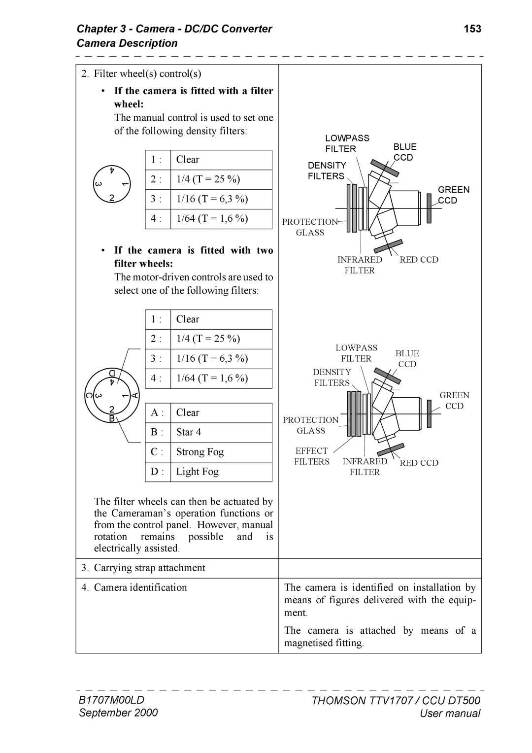
2. Filter wheel(s) control(s) |
|
|
| |||
• If the camera is fitted with a filter |
|
| ||||
| wheel: |
|
|
|
|
|
| The manual control is used to set one |
|
| |||
| of the following density filters: |
| LOWPASS |
| ||
|
|
|
|
| BLUE | |
|
| 1 : | Clear |
| FILTER | |
|
|
| DENSITY | CCD | ||
| 4 |
|
|
|
| |
| 2 : 1/4 (T = 25 %) |
| FILTERS |
| ||
3 | 1 |
| GREEN | |||
| 2 | 3 : 1/16 (T = 6,3 %) |
|
| ||
|
|
| CCD | |||
|
| 4 : 1/64 (T = 1,6 %) |
| PROTECTION |
| |
|
|
|
|
| GLASS |
|
• | If the | camera is fitted with | two |
|
| |
filter wheels: |
|
| INFRARED RED CCD | |||
The | FILTER |
| ||||
|
| |||||
select one of the following filters: |
|
| ||||
|
|
|
|
|
|
|
| 1 : |
| Clear |
|
|
|
|
|
|
|
|
| |
| 2 : | 1/4 (T = 25 %) |
| LOWPASS |
| |
|
|
|
|
| BLUE | |
| 3 : |
| 1/16 (T = 6,3 %) |
| ||
|
|
| FILTER | |||
|
|
| CCD | |||
D |
|
|
|
| DENSITY | |
4 : | 1/64 (T = 1,6 %) |
|
| |||
4 |
| FILTERS |
| |||
|
|
|
|
| ||
3 C | 1 A |
|
|
| GREEN |
2 | A : | Clear |
|
| CCD |
PROTECTION |
|
| |||
B | B : | Star 4 |
|
| |
| GLASS |
|
| ||
| C : | Strong Fog | EFFECT | INFRARED |
|
| D : | Light Fog | FILTERS | RED CCD | |
|
| FILTER |
|
The filter wheels can then be actuated by the Cameraman’s operation functions or from the control panel. However, manual rotation remains possible and is electrically assisted.
3. | Carrying strap attachment |
|
|
|
|
4. | Camera identification | The camera is identified on installation by |
|
| means of figures delivered with the equip- |
|
| ment. |
|
| The camera is attached by means of a |
|
| magnetised fitting. |
B1707M00LD | THOMSON TTV1707 / CCU DT500 |
September 2000 | User manual |