176 | Chapter 4 - Channel control unit |
| Description |
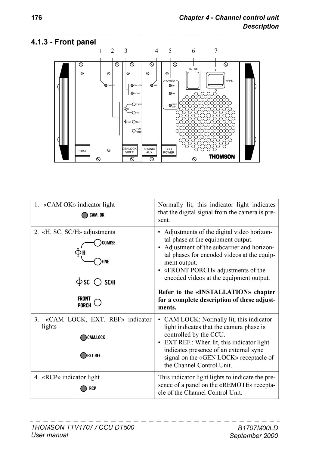
4.1.3 - Front panel
1 | 2 | 3 |
| 4 | 5 | 6 | 7 |
|
|
|
|
|
| ON AIR | I |
|
|
|
|
|
|
| |
|
|
|
|
| CAMERA |
| MAINS |
| CAM. OK |
| CAM.LOCK | RCP | ON |
|
|
|
|
| EXT.REF. |
| OFF |
| O |
|
|
|
|
|
| ||
|
|
| COARSE |
| CABLE |
|
|
|
| H |
|
| OPEN |
|
|
|
|
|
|
|
|
| |
|
|
| FINE |
|
|
|
|
|
| SC | SC/H |
|
|
|
|
|
|
| FRONT |
|
|
|
|
|
|
| PORCH |
|
|
|
|
TRIAX |
| GENLOCK/ | SOUND/ | CCU |
|
| |
| VIDEO | AUX | POWER |
|
| ||
|
|
|
| ||||
1. «CAM OK» indicator light | Normally lit, this indicator light indicates | |||
|
| CAM.OK | that the digital signal from the camera is pre- | |
|
|
|
| sent. |
|
| |||
2. «H, SC, SC/H» adjustments | • Adjustments of the digital video horizon- | |||
| FRONT | COARSE | tal phase at the equipment output. | |
| H |
| • Adjustment of the subcarrier and horizon- | |
|
| FINE | tal phases for encoded videos at the equip- | |
| SC | SC/H | ment output. | |
| • «FRONT PORCH» adjustments of the | |||
| encoded videos at the equipment output. | |||
| PORCH |
| Refer to the «INSTALLATION» chapter | |
|
| for a complete description of these adjust- | ||
|
|
|
| ments. |
|
|
|
| |
3. «CAM LOCK, |
| EXT. REF» indicator | • CAM LOCK: Normally lit, this indicator | |
lights |
| CAM.LOCK | light indicates that the camera phase is | |
|
| controlled by the CCU. | ||
|
| EXT.REF. | • EXT REF.: When lit, this indicator light | |
|
| indicates presence of an external sync | ||
|
|
|
| signal on the «GEN LOCK» receptacle of |
|
|
|
| the Channel Control Unit. |
|
| |||
4. «RCP» indicator light | This indicator light lights to indicate the pre- | |||
|
| RCP | sence of a panel on the «REMOTE» recepta- | |
|
| cle of the Channel Control Unit. | ||
THOMSON TTV1707 / CCU DT500 | B1707M00LD |
User manual | September 2000 |
