Chapter 2 – Mechanical Specifications
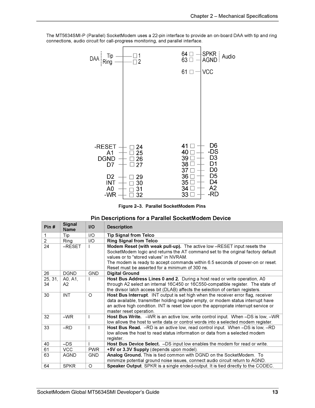
The
|
|
| Figure | |
|
| Pin Descriptions for a Parallel SocketModem Device | ||
Pin # | Signal | I/O | Description | |
Name | ||||
|
|
| ||
1 | Tip | I/O | Tip Signal from Telco | |
2 | Ring | I/O | Ring Signal from Telco | |
24 |
| I | Modem Reset (with weak | |
|
|
| SocketModem logic and returns the AT command set to the original factory default | |
|
|
| values or to "stored values" in NVRAM. | |
|
|
| The modem is ready to accept commands within 6.5 seconds of | |
|
|
| Reset must be asserted for a minimum of 300 ns. | |
26 | DGND | GND | Digital Ground | |
25, 31, | A0, A1, | I | Host Bus Address Lines 0 and 2. During a host read or write operation, A0 | |
34 | A2 |
| through A2 select an internal 16C450 or | |
|
|
| the divisor latch access bit (DLAB) affects the selection of certain registers. | |
30 | INT | O | Host Bus Interrupt. INT output is set high when the receiver error flag, receiver | |
|
|
| data available, transmitter holding register empty, or modem status interrupt have | |
|
|
| an active high condition. INT is reset low upon the appropriate interrupt service or | |
|
|
| master reset operation. | |
32 | I | Host Bus Write. | ||
|
|
| low allows the host to write data or control words into a selected modem register. | |
33 | I | Host Bus Read. | ||
|
|
| low allows the host to read status information or data from a selected modem | |
|
|
| register. | |
40 | I | Host Bus Device Select. | ||
61 | VCC | PWR | +5V or 3.3V Supply (depends upon model). | |
63 | AGND | GND | Analog Ground. This is tied common with DGND on the SocketModem. To | |
|
|
| minimize potential ground noise issues, connect audio circuit return to AGND. | |
64 | SPKR | O | Speaker Output. SPKR is a single | |
SocketModem Global MT5634SMI Developer’s Guide | 13 |
