Teledyne API Model 465L O3 Monitor Operation Manual
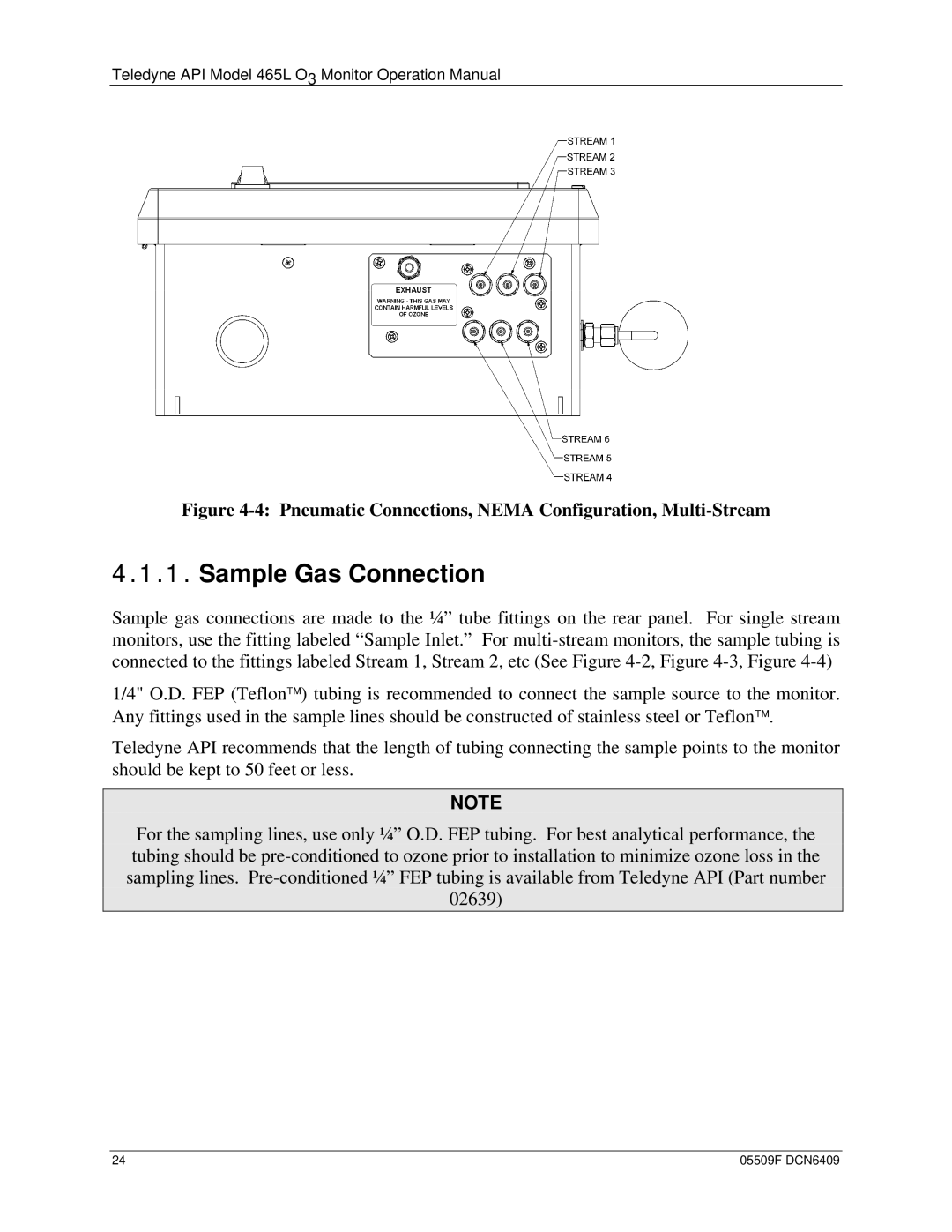
Figure 4-4: Pneumatic Connections, NEMA Configuration, Multi-Stream
4.1.1.Sample Gas Connection
Sample gas connections are made to the ¼” tube fittings on the rear panel. For single stream monitors, use the fitting labeled “Sample Inlet.” For
1/4" O.D. FEP (Teflon™) tubing is recommended to connect the sample source to the monitor. Any fittings used in the sample lines should be constructed of stainless steel or Teflon™.
Teledyne API recommends that the length of tubing connecting the sample points to the monitor should be kept to 50 feet or less.
NOTE
For the sampling lines, use only ¼” O.D. FEP tubing. For best analytical performance, the tubing should be
24 | 05509F DCN6409 |
