2 Installation | Model 7300A | |
|
|
|
|
|
|
|
|
|
2.3.1 Primary Input Power
The power cord receptacle and fuse block are located in the same assembly. Insert the power cord into the power cord receptacle.
DANGER: POWER IS APPLIED TO THE INSTRUMENT'S CIR- CUITRY AS LONG AS THE INSTRUMENT IS CON- NECTED TO THE POWER SOURCE. THE STANDBY ON THE FRONT PANEL IS FOR SWITCHING POWER ON OR OFF TO THE DISPLAYS AND OUT- PUTS ONLY.
The standard power supply requires a 110 V ac,
2.3.2 Fuse Installation
The fuse block, at the right of the power cord receptacle, accepts US or European size fuses. A jumper replaces the fuse in whichever fuse receptacle is not used.
2.3.3 50-Pin Equipment Interface Connector
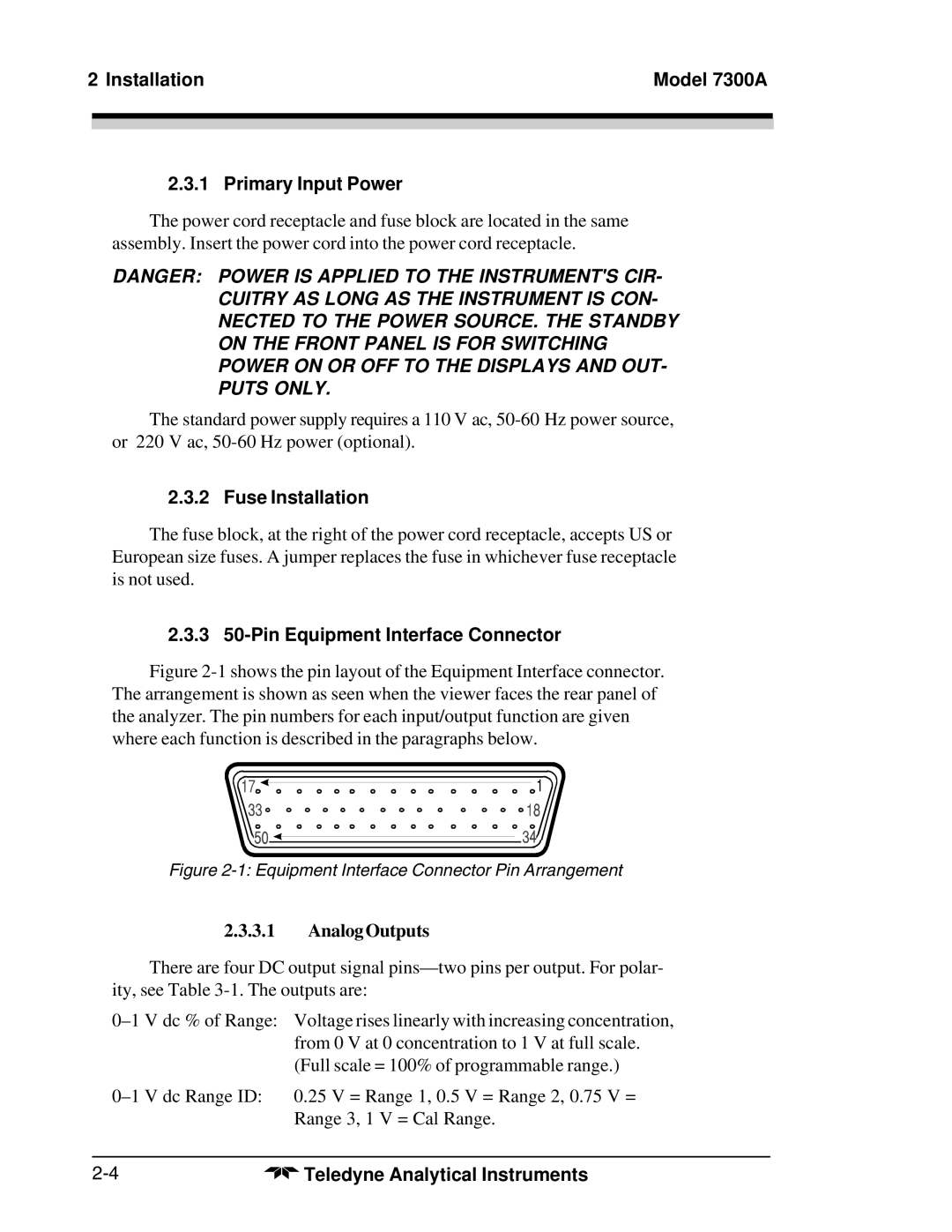
Figure 2-1 shows the pin layout of the Equipment Interface connector. The arrangement is shown as seen when the viewer faces the rear panel of the analyzer. The pin numbers for each input/output function are given where each function is described in the paragraphs below.
Figure 2-1: Equipment Interface Connector Pin Arrangement
2.3.3.1Analog Outputs
There are four DC output signal
Range 1, 0.5 V = Range 2, 0.75 V = | |
Range 3, | 1 V = Cal Range. |
Teledyne Analytical Instruments |