2 Installation | Model 7300A | |
|
|
|
|
|
|
|
|
|
6 | 0.6 | 13.6 |
7 | 0.7 | 15.2 |
8 | 0.8 | 16.8 |
9 | 0.9 | 18.4 |
10 | 1.0 | 20.0 |
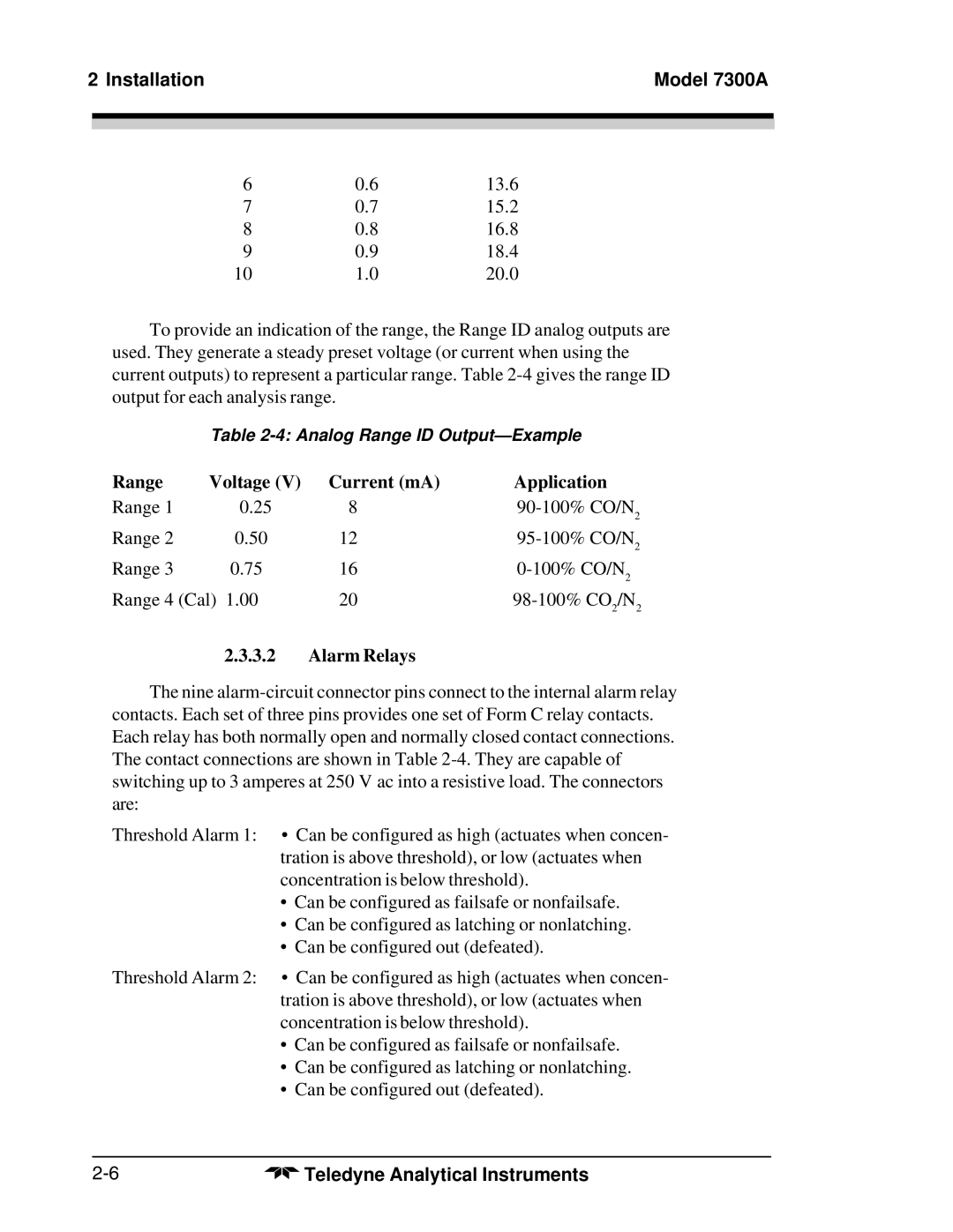
To provide an indication of the range, the Range ID analog outputs are used. They generate a steady preset voltage (or current when using the current outputs) to represent a particular range. Table
Table
Range | Voltage (V) | Current (mA) | Application |
Range 1 | 0.25 | 8 | |
Range 2 | 0.50 | 12 | |
Range 3 | 0.75 | 16 | |
Range 4 (Cal) 1.00 | 20 | ||
2.3.3.2Alarm Relays
The nine
Threshold Alarm 1: • Can be configured as high (actuates when concen- tration is above threshold), or low (actuates when concentration is below threshold).
•Can be configured as failsafe or nonfailsafe.
•Can be configured as latching or nonlatching.
•Can be configured out (defeated).
Threshold Alarm 2: • Can be configured as high (actuates when concen- tration is above threshold), or low (actuates when concentration is below threshold).
•Can be configured as failsafe or nonfailsafe.
•Can be configured as latching or nonlatching.
•Can be configured out (defeated).
Teledyne Analytical Instruments |
