Infrared Gas Analyzer | Installation 2 | |
|
|
|
|
|
|
|
|
|
Table
Pin Function
3+ Range ID,
4– Range ID,
5+ % Range,
6– % Range,
8+ Range ID,
23– Range ID,
24+ % Range,
7 – % Range,
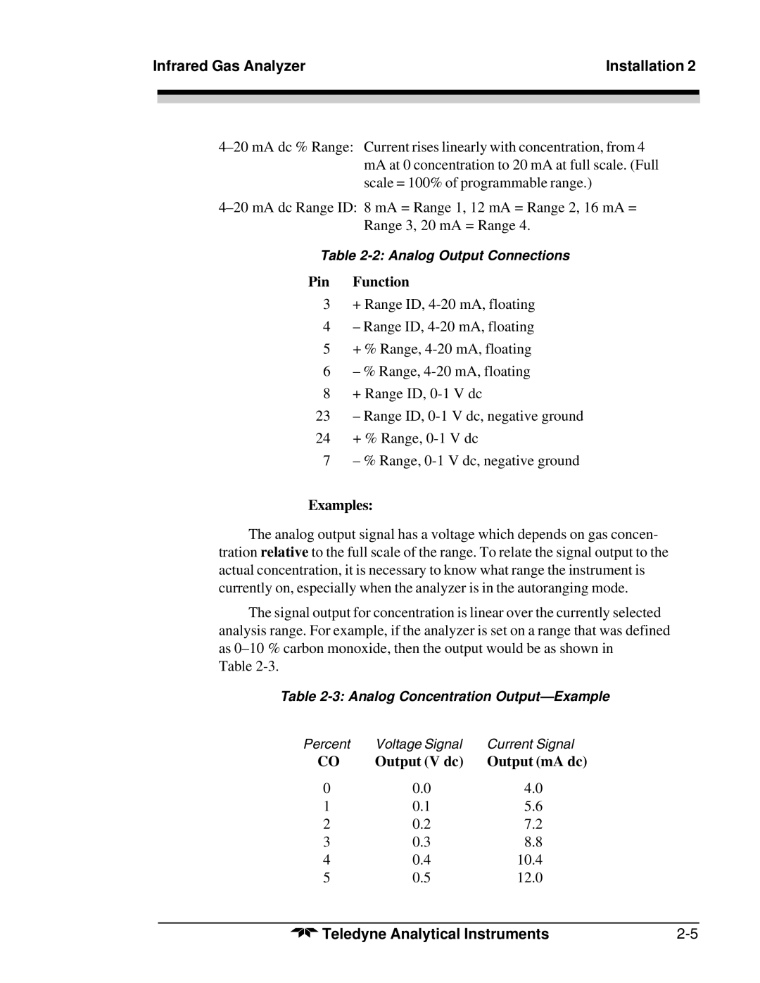
Examples:
The analog output signal has a voltage which depends on gas concen- tration relative to the full scale of the range. To relate the signal output to the actual concentration, it is necessary to know what range the instrument is currently on, especially when the analyzer is in the autoranging mode.
The signal output for concentration is linear over the currently selected analysis range. For example, if the analyzer is set on a range that was defined as
Table
Table
Percent | Voltage Signal | Current Signal |
CO | Output (V dc) | Output (mA dc) |
0 | 0.0 | 4.0 |
1 | 0.1 | 5.6 |
2 | 0.2 | 7.2 |
3 | 0.3 | 8.8 |
4 | 0.4 | 10.4 |
5 | 0.5 | 12.0 |
Teledyne Analytical Instruments |