MSP430x11x1
MIXED SIGNAL MICROCONTROLLER
SLAS241C ± SEPTEMBER 1999 ± REVISED JUNE 2000
oscillator and system clock (continued)
| DIVA |
|
| 2 |
|
LFXT1CLK |
| ACLK |
| /1, /2, /4, /8 | |
OSCOff XTS |
| Auxiliary Clock |
|
| |
XIN | ACLKGEN |
|
SELM | DIVM CPUOff |
|
LFXT1 OSCILLATOR |
|
|
2 | 2 |
|
3 |
|
|
0,1 | /1, /2, /4, /8, Off | MCLK |
XOUT | ||
2 |
| Main System Clock |
DCOCLK | MCLKGEN |
|
|
|
VCCVCC
Rsel SCG0 | DCO | MOD |
|
| ||||
| 3 |
| 5 |
|
| SELS | DIVS | SCG1 |
|
|
| ||||||
|
|
|
|
| 2 |
| ||
|
|
|
|
|
|
|
| |
|
|
|
|
|
|
|
|
|
| 0 | Digital Controlled Oscillator (DCO) | 0 |
|
| DC |
| ||
| + | /1, /2, /4, /8, Off | SMCLK | |
| Generator | |||
| Modulator (MOD) |
| Subsystem Clock | |
| 1 | 1 | ||
|
| |||
P2.5/Rosc |
|
| ||
|
|
| ||
DCGEN | DCOMOD | SMCLKGEN |
| |
|
| |||
| DCOR |
|
|
|
|
| The |
| |
|
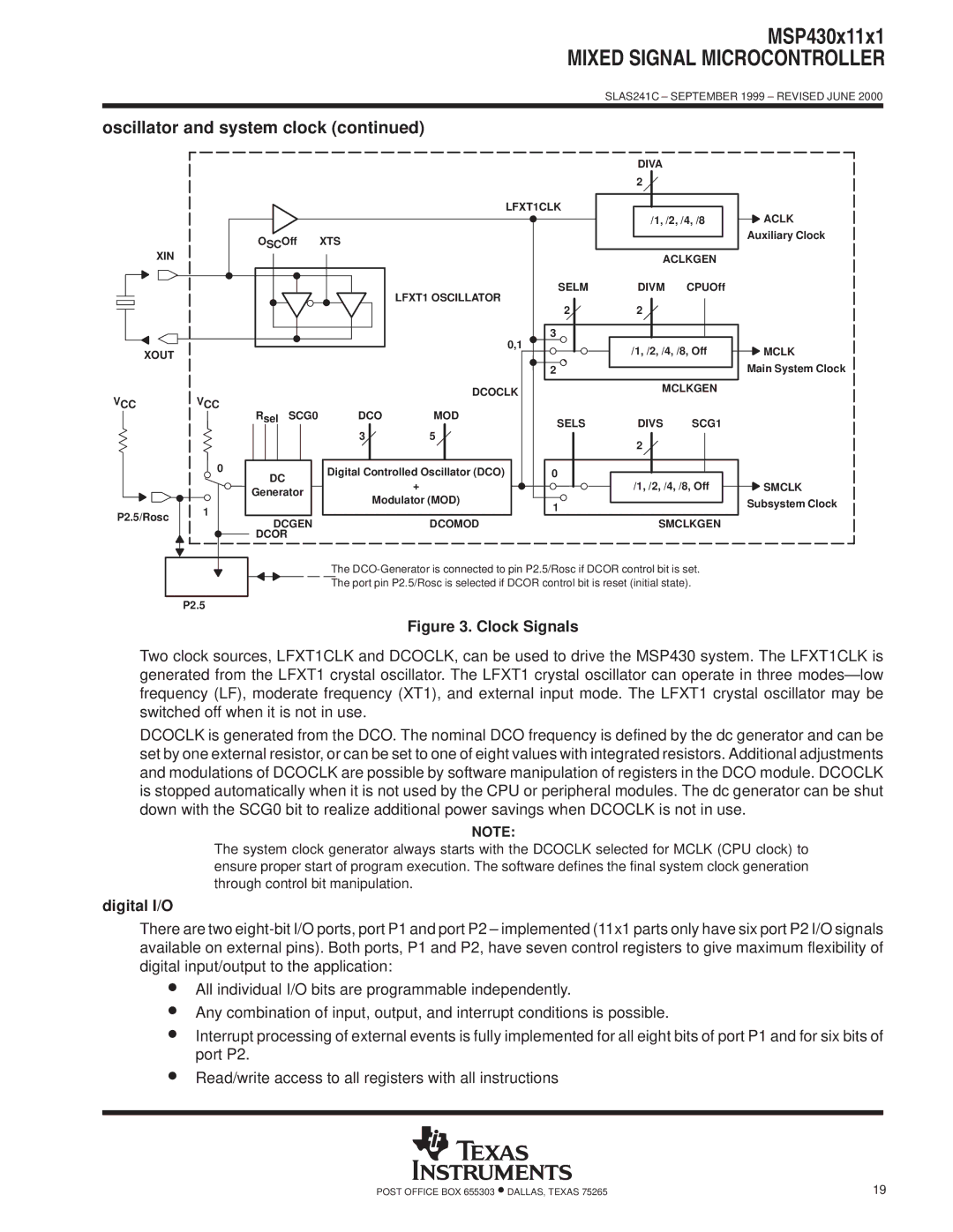
| The port pin P2.5/Rosc is selected if DCOR control bit is reset (initial state). |
| |
P2.5
Figure 3. Clock Signals
Two clock sources, LFXT1CLK and DCOCLK, can be used to drive the MSP430 system. The LFXT1CLK is generated from the LFXT1 crystal oscillator. The LFXT1 crystal oscillator can operate in three modesÐlow frequency (LF), moderate frequency (XT1), and external input mode. The LFXT1 crystal oscillator may be switched off when it is not in use.
DCOCLK is generated from the DCO. The nominal DCO frequency is defined by the dc generator and can be set by one external resistor, or can be set to one of eight values with integrated resistors. Additional adjustments and modulations of DCOCLK are possible by software manipulation of registers in the DCO module. DCOCLK is stopped automatically when it is not used by the CPU or peripheral modules. The dc generator can be shut down with the SCG0 bit to realize additional power savings when DCOCLK is not in use.
NOTE:
The system clock generator always starts with the DCOCLK selected for MCLK (CPU clock) to ensure proper start of program execution. The software defines the final system clock generation through control bit manipulation.
digital I/O
There are two
•All individual I/O bits are programmable independently.
•Any combination of input, output, and interrupt conditions is possible.
•Interrupt processing of external events is fully implemented for all eight bits of port P1 and for six bits of port P2.
•Read/write access to all registers with all instructions
POST OFFICE BOX 655303 •DALLAS, TEXAS 75265 | 19 |