ASSEMBLY
CONTINUOUS DUTY SOLENOID SWITCH
Mount the solenoid switch, drill holes to match if necessary, mount in dry and well protected area. Secure as shown in the parts section.
A.) ORANGE 10 GA. wire from terminal (D) to +12V battery post on tractor starter solenoid. B.) RED 14 GA. wire from terminal (C) to tractor plug in cab.
C.) BLACK 14 GA. wire from terminal (B) to tractor common ground. D.) RED 10 GA. wire from terminal (A) to switch box.
E.) RED 14 GA. wire from terminal (A) to temperature gauge. (optional) F.) GREEN 10 GA. wire from switchbox to (B) on cooler fan connector. G.) ORANGE 10 GA. wire from switchbox to (A) on cooler fan connector.
H.) ORANGE 16 GA. wire from switchbox to (A) on Mower Run (Right) connector. I.) BLACK 16 GA. wire from switchbox to (B) on Mower Run (Right) connector.
J.) WHITE 16 GA. wire from switchbox to (A) on Mower Run (Left/Rear) connector. K.) BLACK 16 GA. wire from switchbox to (B) on Mower Run (Left/Rear)
connector.
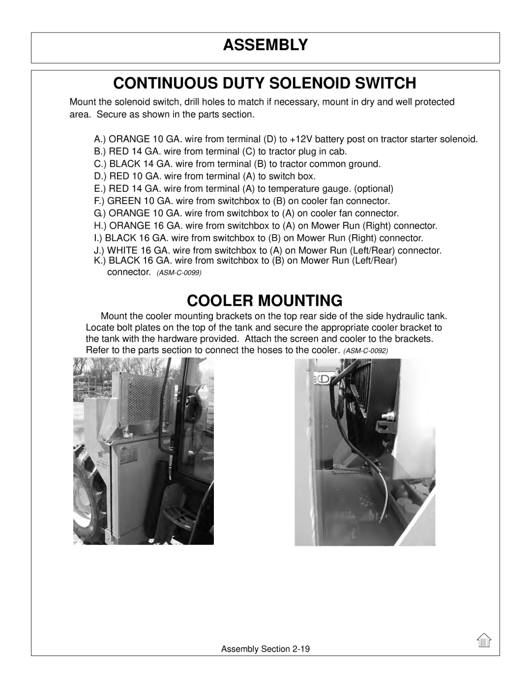
COOLER MOUNTING
Mount the cooler mounting brackets on the top rear side of the side hydraulic tank. Locate bolt plates on the top of the tank and secure the appropriate cooler bracket to the tank with the hardware provided. Attach the screen and cooler to the brackets. Refer to the parts section to connect the hoses to the cooler.
Assembly Section