10.6Join the Auxiliary Cabinet with the UPS
The Toshiba Auxiliary Cabinet (431A) is equipped with four 14 mm mating holes located on the front and back of the left and right sides of the cabinet.
1.Remove the top and bottom 431A Cabinet Front panels.
2.Remove the cable access plate at the
3.Remove the cable access plate at the
4.Position the 431A cabinet to the left of and adjacent to the UPS Cabinet.
5.Align the four 0.63 in (14 mm) bolt holes on the right side of the 431A Cabinet with the matching four 14 mm bolt holes on the left side of the UPS Cabinet.
6.Bolt the cabinets together with four
7.Select the power cables per Table 10.2 /Table 10.3. Cable size for the UTILITY and LOAD terminals are dependant on the Input/Output Voltages to the transformers. The UPS Input/Output cables will be the same size: 3Phase/4Wire 208/120V.
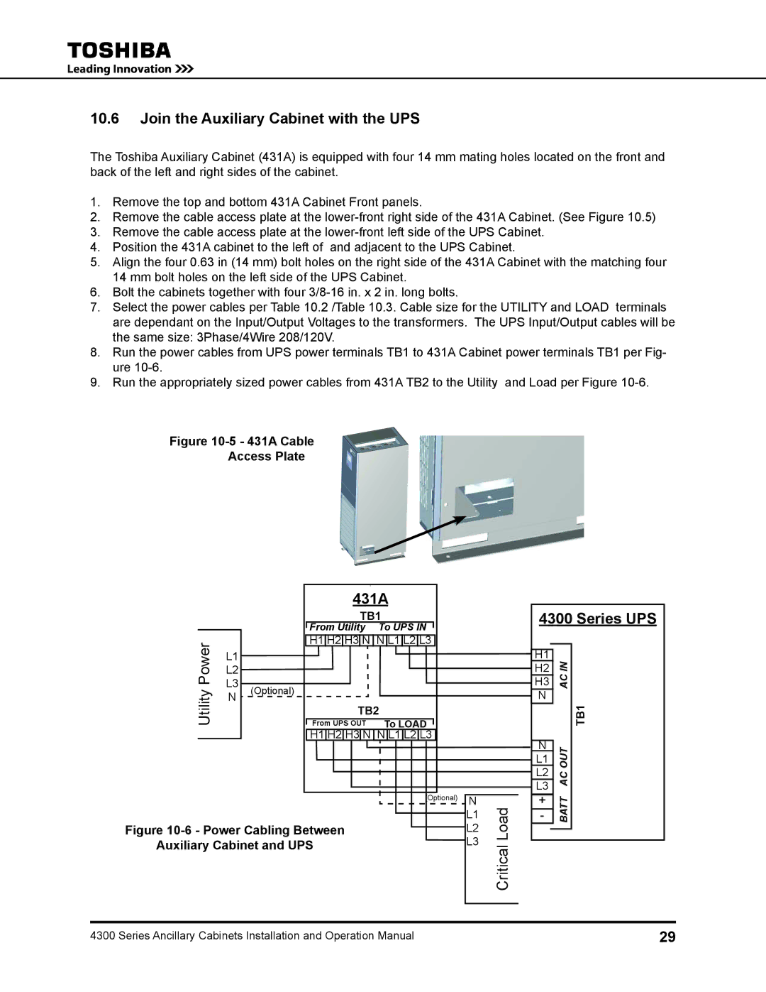
8.Run the power cables from UPS power terminals TB1 to 431A Cabinet power terminals TB1 per Fig- ure
9.Run the appropriately sized power cables from 431A TB2 to the Utility and Load per Figure
Figure 10-5 - 431A Cable
Access Plate
|
|
|
|
|
|
|
|
|
| 1 |
|
|
|
|
|
|
|
|
|
|
|
|
|
| 431A |
| |||||||
|
|
|
|
|
|
|
|
| TB1 |
| ||||||
|
|
|
|
| From Utility |
| To UPS IN |
|
| |||||||
|
|
|
|
|
|
|
| |||||||||
Power |
|
|
| H1 | H2 | H3 | N | N | L1 | L2 | L3 |
| ||||
L1 |
|
|
|
|
|
|
|
|
|
|
|
|
|
| ||
|
|
|
|
|
|
|
|
|
|
|
|
|
|
|
| |
|
| L2 |
|
|
|
|
|
|
|
|
|
|
|
|
|
|
|
| L3 |
|
|
|
|
|
|
|
|
|
|
|
|
|
|
Utility | (Optional) |
|
|
|
|
|
|
| ||||||||
N |
| To LOAD |
| |||||||||||||
|
| From UPS OUT |
|
| ||||||||||||
|
|
|
|
|
|
|
| TB2 |
| |||||||
|
|
|
|
|
|
|
|
|
|
|
|
|
|
|
|
|
|
|
|
|
|
|
|
|
|
|
|
|
|
| |||
|
|
|
|
| H1 H2 H3 N N L1 L2 L3 |
| ||||||||||
|
|
|
|
|
|
|
|
|
|
|
|
|
|
|
|
|
|
|
|
| (Optional) | N | |
|
|
|
|
|
|
| L1 |
|
|
|
|
|
|
| |
Figure |
|
| L2 | ||||
|
| ||||||
Auxiliary Cabinet and UPS | L3 | ||||||
|
|
|
|
|
|
|
|
Critical Load
4300 Series UPS
|
|
|
|
H1 | IN |
| |
H2 |
| ||
|
| AC |
|
H3 |
| ||
N |
| TB1 | |
|
|
| |
|
|
| |
N | OUT |
| |
L1 |
|
| |
L2 | AC |
| |
L3 |
| ||
|
| ||
+ |
| BATT |
|
- |
|
| |
|
|
|
|
4300 Series Ancillary Cabinets Installation and Operation Manual | 29 |