11 431B - Toshiba Battery Cabinet
1
2
3
12
13
431B - Door Closed
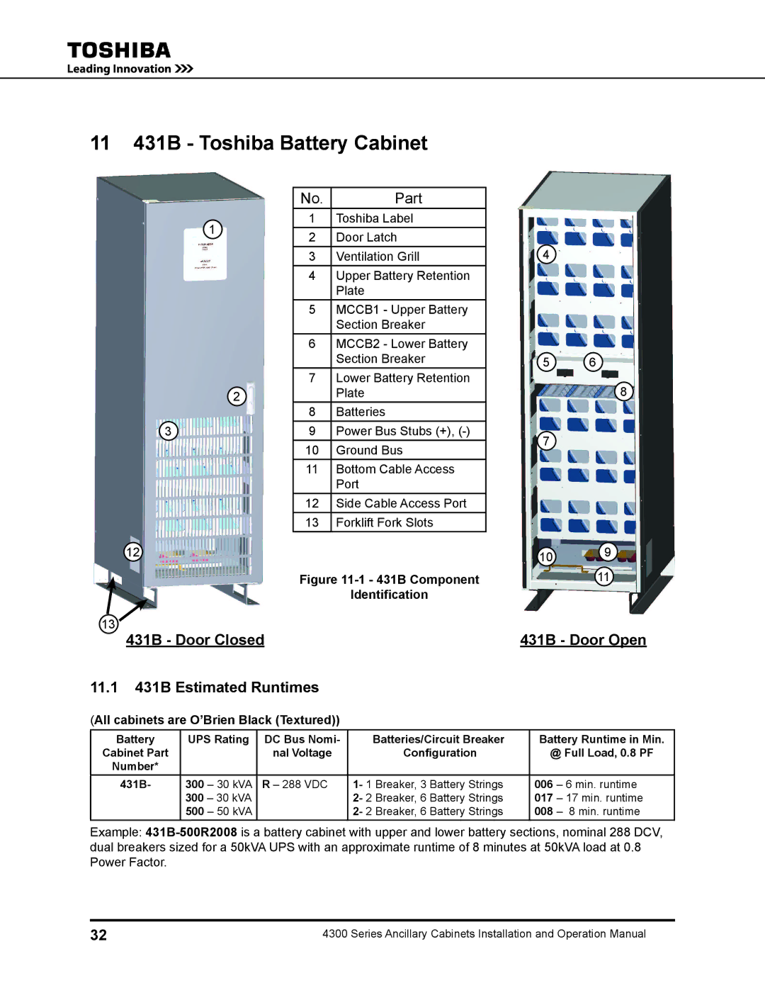
No. | Part |
1 | Toshiba Label |
2 | Door Latch |
3 | Ventilation Grill |
4 | Upper Battery Retention |
| Plate |
5 | MCCB1 - Upper Battery |
| Section Breaker |
6 | MCCB2 - Lower Battery |
| Section Breaker |
7 | Lower Battery Retention |
| Plate |
8 | Batteries |
9 | Power Bus Stubs (+), |
10 | Ground Bus |
11 | Bottom Cable Access |
| Port |
12 | Side Cable Access Port |
13 | Forklift Fork Slots |
Figure 11-1 - 431B Component
Identification
4
5 6
8
7
109
11
431B - Door Open
11.1431B Estimated Runtimes
(All cabinets are O’Brien Black (Textured))
Battery | UPS Rating | DC Bus Nomi- | Batteries/Circuit Breaker | Battery Runtime in Min. | |
Cabinet Part |
| nal Voltage | Configuration | @ Full Load, 0.8 PF | |
Number* |
|
|
|
|
|
431B- | 300 – 30 kVA | R – 288 VDC | 1- 1 Breaker, 3 Battery Strings | 006 | – 6 min. runtime |
| 300 – 30 kVA |
| 2- 2 Breaker, 6 Battery Strings | 017 | – 17 min. runtime |
| 500 – 50 kVA |
| 2- 2 Breaker, 6 Battery Strings | 008 | – 8 min. runtime |
Example:
32 | 4300 Series Ancillary Cabinets Installation and Operation Manual |