13.6Join the 431M Cabinet with the UPS
The 431M is equipped with four 16 mm mating holes located on the front and back of the left and right sides of the cabinet.
DANGER: HAZARDOUS VOLTAGES MAY EXIST.
Verify all power is removed from the UPS and power cables prior connecting the power cables to the Auxiliary Cabinet terminals, Maintenance Bypass Switch terminals, or UPS terminals.
1.Remove the top and bottom 431M Cabinet Front panels.
2.Remove the cable access plate at the
3.Remove the cable access plate at the
4.Position the 431M cabinet to the left of and adjacent to the UPS Cabinet.
5.Place the 431M base over the floor anchor bolts (if available). (Figure
6.Align the four 14 mm bolt holes on the right side of the 431M Cabinet with the matching four 16 mm bolt holes on the left side of the UPS Cabinet.
7.Bolt the cabinets together with four
8.Secure 431M base anchor bolts.
9.Select the power cables per Tables
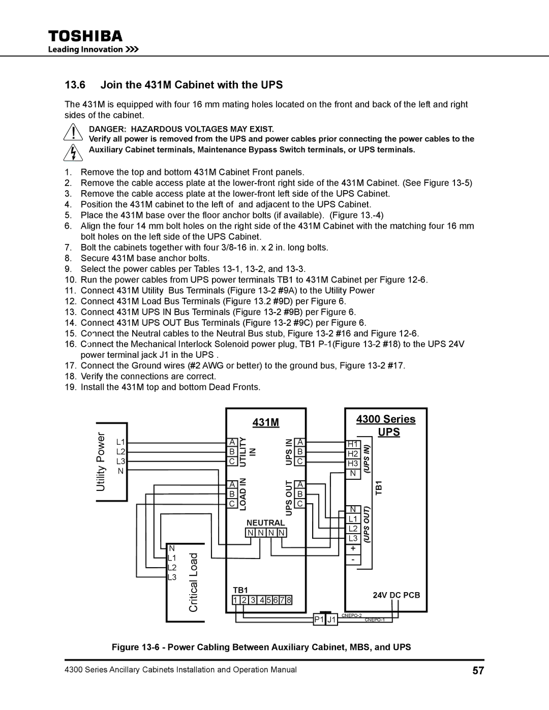
10.Run the power cables from UPS power terminals TB1 to 431M Cabinet per Figure
11.Connect 431M Utility Bus Terminals (Figure
12.Connect 431M Load Bus Terminals (Figure 13.2 #9D) per Figure 6.
13.Connect 431M UPS IN Bus Terminals (Figure
14.Connect 431M UPS OUT Bus Terminals (Figure
15.Connect the Neutral cables to the Neutral Bus stub, Figure
16.Connect the Mechanical Interlock Solenoid power plug, TB1
17.Connect the Ground wires (#2 AWG or better) to the ground bus, Figure
18.Verify the connections are correct.
19.Install the 431M top and bottom Dead Fronts.
Utility Power
L1
L2
L3
N
N
L1
L2
L3
Load
431M
A |
| UPSIN | A | |
C UTILITYIN | C | |||
B |
|
| B | |
A | LOADIN | OUTUPS | A | |
B | B | |||
|
| |||
C |
|
| C | |
NEUTRAL
N N N N
4300 Series
UPS
|
|
|
|
|
H1 |
| IN) |
| |
|
| |||
H2 |
|
| ||
| (UPS |
| ||
H3 |
|
| ||
|
|
| ||
N |
|
| TB1 | |
|
|
|
| |
N |
| OUT) |
| |
|
| |||
L1 |
|
| ||
L2 |
| (UPS |
| |
L3 |
|
| ||
+ |
|
|
|
|
- |
|
|
|
|
|
|
|
|
|
Critical
TB1 |
|
|
|
|
| 24V DC PCB | |||
1 | 2 | 3 | 4 | 5 | 6 | 7 | 8 | ||
| |||||||||
P1 J1 |
Figure 13-6 - Power Cabling Between Auxiliary Cabinet, MBS, and UPS
4300 Series Ancillary Cabinets Installation and Operation Manual | 57 |