8.2 Removing the Front Bezel
Care must be taken to ensure that the latches on the front bezel used to attach it to the system chassis does not break. Follow this procedure to detach it from the system chassis:
1.Open the cabinet cover (see the previous section in this chapter).
2.Remove the primary hard disk drive (see chapter 2 on Installing a Hard Disk Drive).
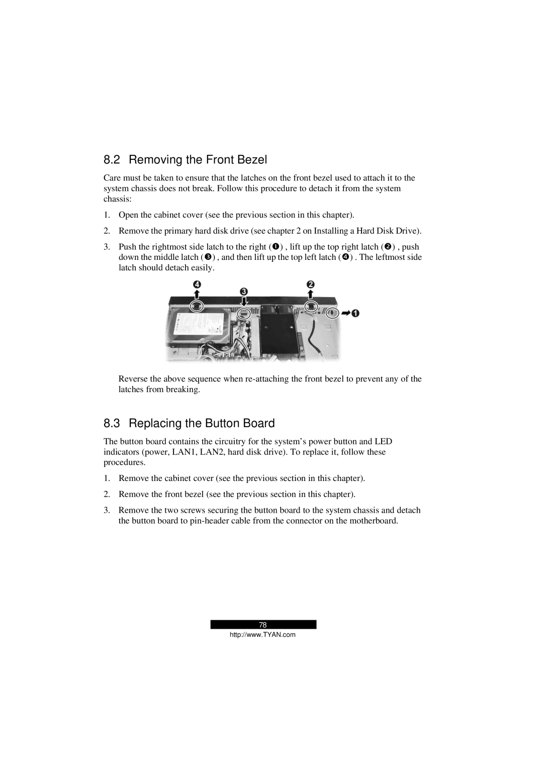
3.Push the rightmost side latch to the right (Œ) , lift up the top right latch (•) , push down the middle latch (Ž) , and then lift up the top left latch (•) . The leftmost side latch should detach easily.
Reverse the above sequence when
8.3 Replacing the Button Board
The button board contains the circuitry for the system’s power button and LED indicators (power, LAN1, LAN2, hard disk drive). To replace it, follow these procedures.
1.Remove the cabinet cover (see the previous section in this chapter).
2.Remove the front bezel (see the previous section in this chapter).
3.Remove the two screws securing the button board to the system chassis and detach the button board to
78
http://www.TYAN.com