www.unicomlink.com | UNICOM |
Off
No device attached or in
Table
Rear Panel
The
Figure 2-3. The Rear Panel of SmartGST-2402M
Desktop Installation 
Set the Switch on a sufficiently large flat space with a power outlet nearby. The surface where you put your Switch should be clean, smooth, level and sturdy. Make sure there is enough clearance around the Switch to allow attachment of cables, power cord and allow air circulation.
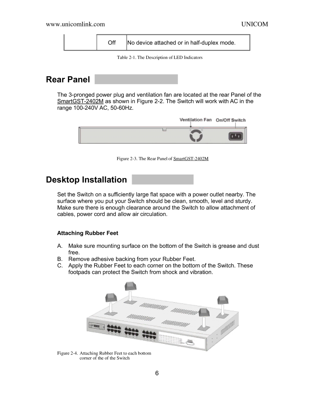
Attaching Rubber Feet
A.Make sure mounting surface on the bottom of the Switch is grease and dust free.
B.Remove adhesive backing from your Rubber Feet.
C.Apply the Rubber Feet to each corner on the bottom of the Switch. These footpads can protect the Switch from shock and vibration.
Figure 2-4. Attaching Rubber Feet to each bottom
corner of the of the Switch
6