REPEATER OPERATION
MANUAL REPEATER SHIFT ACTIVATION
Checking the Repeater Uplink (Input) Frequency
It often is helpful to be able to check the uplink (input) frequency of a repeater, to see if the calling station is within direct (“Simplex”) range.
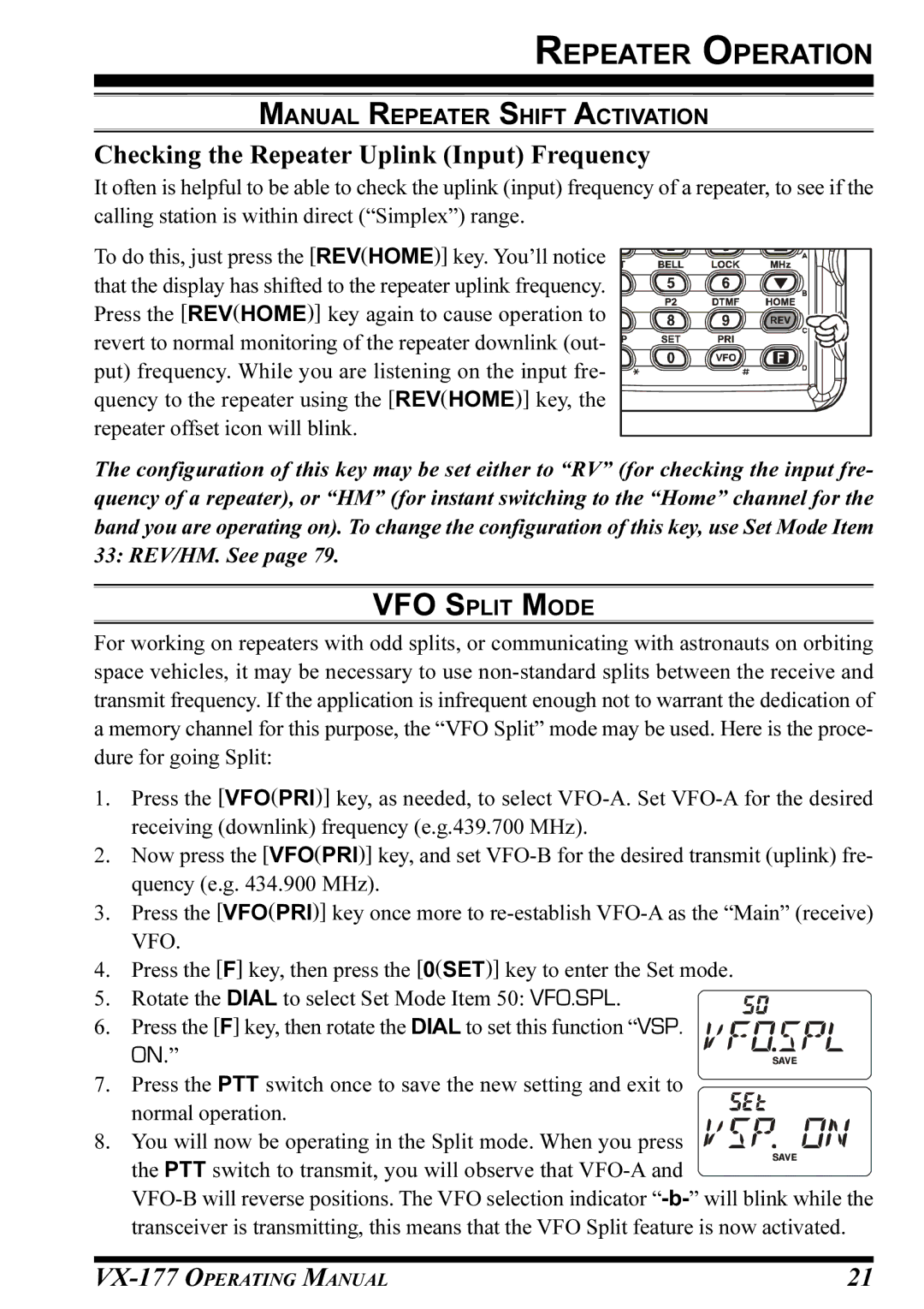
To do this, just press the [REV(HOME)] key. You’ll notice ![]() that the display has shifted to the repeater uplink frequency.
that the display has shifted to the repeater uplink frequency. ![]()
![]()
![]()
![]()
![]()
![]() Press the [REV(HOME)] key again to cause operation to
Press the [REV(HOME)] key again to cause operation to ![]()
![]()
![]()
![]()
![]() revert to normal monitoring of the repeater downlink (out-
revert to normal monitoring of the repeater downlink (out- ![]()
![]()
![]()
![]() put) frequency. While you are listening on the input fre-
put) frequency. While you are listening on the input fre- ![]()
![]()
![]()
![]()
![]() quency to the repeater using the [REV(HOME)] key, the
quency to the repeater using the [REV(HOME)] key, the![]() repeater offset icon will blink.
repeater offset icon will blink.
The configuration of this key may be set either to “RV” (for checking the input fre- quency of a repeater), or “HM” (for instant switching to the “Home” channel for the band you are operating on). To change the configuration of this key, use Set Mode Item 33: REV/HM. See page 79.
VFO SPLIT MODE
For working on repeaters with odd splits, or communicating with astronauts on orbiting space vehicles, it may be necessary to use
1.Press the [VFO(PRI)] key, as needed, to select
2.Now press the [VFO(PRI)] key, and set
3.Press the [VFO(PRI)] key once more to
4.Press the [F] key, then press the [0(SET)] key to enter the Set mode.
5. Rotate the DIAL to select Set Mode Item 50: VFO.SPL.
6. Press the [F] key, then rotate the DIAL to set this function “VSP. ON.”
7. Press the PTT switch once to save the new setting and exit to
normal operation. 8. You will now be operating in the Split mode. When you press
the PTT switch to transmit, you will observe that
21 |