VIVOTEK
DI/DO Diagram
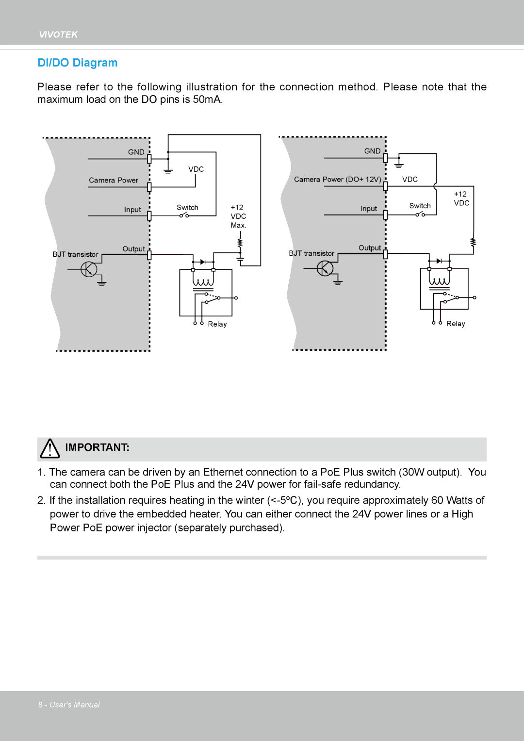
Please refer to the following illustration for the connection method. Please note that the maximum load on the DO pins is 50mA.
GND
Camera Power
Input
BJT transistor |
|
| Output | |||||
|
|
| ||||||
|
|
|
|
|
|
|
|
|
|
|
|
|
|
|
|
|
|
|
|
|
|
|
|
|
|
|
|
|
|
|
|
|
|
|
|
VDC |
|
Switch | +12 |
| VDC |
| Max. |
Relay |
| GND |
|
|
Camera Power (DO+ 12V) | VDC |
| |
|
|
| +12 |
| Input | Switch | VDC |
|
| ||
|
|
| |
BJT transistor | Output |
|
|
|
|
| |
Relay |
![]() IMPORTANT:
IMPORTANT:
1.The camera can be driven by an Ethernet connection to a PoE Plus switch (30W output). You can connect both the PoE Plus and the 24V power for
2.If the installation requires heating in the winter
8 - User's Manual