Vixel Model 335 Installation & Configuration Guide | CHAPTER 2 Installation | |||
|
|
|
|
|
|
|
|
|
|
| System LEDs |
| Indication |
|
|
|
|
| |
| Power | When lit, the switch is plugged in and the internal power |
| |
| (green LED) | supply is functional. |
|
|
|
|
|
| |
| Switch Fault | Indicates that the internal hardware |
| |
| (yellow LED) | lit, the switch will not function. |
| |
|
| Indicates that a fan has stopped operating or the ambient |
| |
|
| temperature has exceeded 45°C. When lit, the switch is still |
| |
|
| functional but requires immediate attention. The LED will |
| |
|
| turn off when the detected condition is corrected. |
| |
|
|
|
| |
| Switch Op | Indicates whether the zones are initialized and operational. |
| |
| (green LED) | If the Switch Op LED is lit, all zones with inserted devices |
| |
|
| are operational. If the Switch Op LED is blinking in a |
| |
|
| multiple zone configuration, one or more zones are |
| |
|
| operational while others are not. If the Switch Op LED is |
| |
|
| off, no operational zones exist or no devices are attached. |
| |
|
|
|
| |
| 2 Gb/s | Indicates the current operational speed of the switch. When |
| |
| (green LED) | lit, the switch is operating at 2 Gb/s. If unlit, the switch is |
| |
|
| operating at 1 Gb/s. |
|
|
|
|
|
| |
| Mgmt Present | Indicates that switch management is functioning. If |
| |
| (yellow LED) | flashing, indicates that management functionality has failed |
| |
|
| and is not communicating with the switch. |
| |
|
|
|
| |
| Enet Active | Indicates Ethernet activity on the switch and is controlled |
| |
| (green LED) | through the Ethernet transceiver. |
| |
|
|
|
|
|
Port LEDs
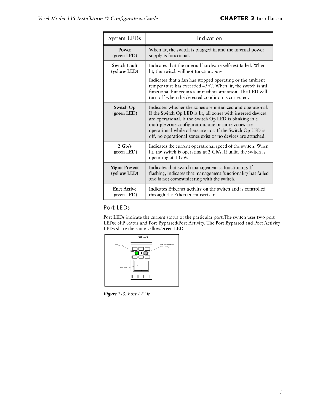
Port LEDs indicate the current status of the particular port.The switch uses two port
LEDs: SFP Status and Port Bypassed/Port Activity. The Port Bypassed and Port Activity
LEDs share the same yellow/green LED.
Figure 2-3. Port LEDs
7
