VXI Technology, Inc.
BRACKETING A VOLTAGE
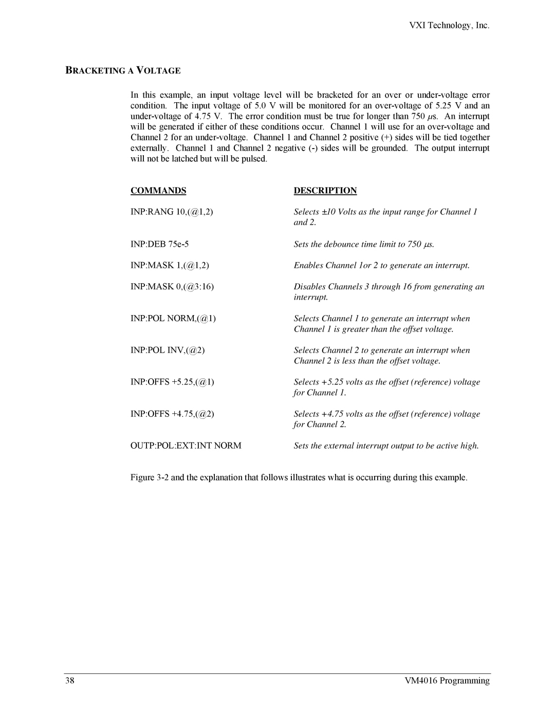
In this example, an input voltage level will be bracketed for an over or
COMMANDS | DESCRIPTION |
INP:RANG 10,(@1,2) | Selects ±10 Volts as the input range for Channel 1 |
| and 2. |
INP:DEB | Sets the debounce time limit to 750 ∝s. |
INP:MASK 1,(@1,2) | Enables Channel 1or 2 to generate an interrupt. |
INP:MASK 0,(@3:16) | Disables Channels 3 through 16 from generating an |
| interrupt. |
INP:POL NORM,(@1) | Selects Channel 1 to generate an interrupt when |
| Channel 1 is greater than the offset voltage. |
INP:POL INV,(@2) | Selects Channel 2 to generate an interrupt when |
| Channel 2 is less than the offset voltage. |
INP:OFFS +5.25,(@1) | Selects +5.25 volts as the offset (reference) voltage |
| for Channel 1. |
INP:OFFS +4.75,(@2) | Selects +4.75 volts as the offset (reference) voltage |
| for Channel 2. |
OUTP:POL:EXT:INT NORM | Sets the external interrupt output to be active high. |
Figure 3-2 and the explanation that follows illustrates what is occurring during this example.
38 | VM4016 Programming |
