ACC/ ![]()
![]() FAIL ERR
FAIL ERR
J200
ACC/ ![]()
![]() FAIL ERR
FAIL ERR
J201
ACC/ ![]()
![]() FAIL ERR
FAIL ERR
J202 |
bus |
VXI Technology, Inc.
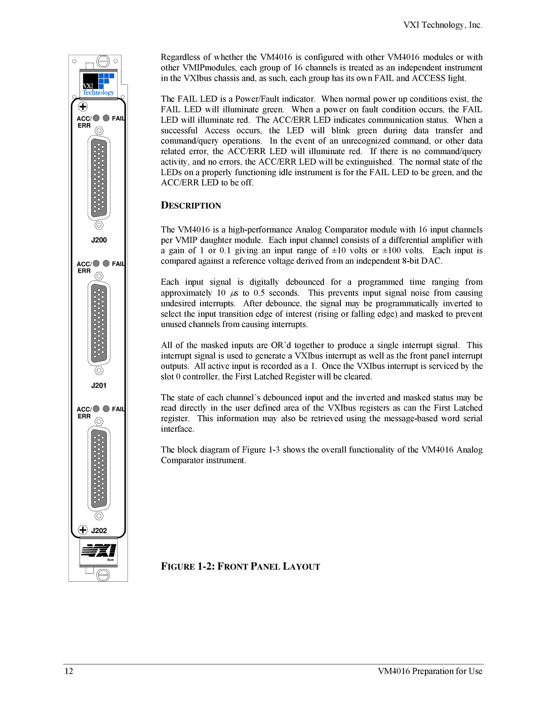
Regardless of whether the VM4016 is configured with other VM4016 modules or with other VMIPmodules, each group of 16 channels is treated as an independent instrument in the VXIbus chassis and, as such, each group has its own FAIL and ACCESS light.
The FAIL LED is a Power/Fault indicator. When normal power up conditions exist, the FAIL LED will illuminate green. When a power on fault condition occurs, the FAIL LED will illuminate red. The ACC/ERR LED indicates communication status. When a successful Access occurs, the LED will blink green during data transfer and command/query operations. In the event of an unrecognized command, or other data related error, the ACC/ERR LED will illuminate red. If there is no command/query activity, and no errors, the ACC/ERR LED will be extinguished. The normal state of the LEDs on a properly functioning idle instrument is for the FAIL LED to be green, and the ACC/ERR LED to be off.
DESCRIPTION
The VM4016 is a
Each input signal is digitally debounced for a programmed time ranging from approximately 10 ∝s to 0.5 seconds. This prevents input signal noise from causing undesired interrupts. After debounce, the signal may be programmatically inverted to select the input transition edge of interest (rising or falling edge) and masked to prevent unused channels from causing interrupts.
All of the masked inputs are OR’d together to produce a single interrupt signal. This interrupt signal is used to generate a VXIbus interrupt as well as the front panel interrupt outputs. All active input is recorded as a 1. Once the VXIbus interrupt is serviced by the slot 0 controller, the First Latched Register will be cleared.
The state of each channel’s debounced input and the inverted and masked status may be read directly in the user defined area of the VXIbus registers as can the First Latched register. This information may also be retrieved using the
The block diagram of Figure
FIGURE 1-2: FRONT PANEL LAYOUT
12 | VM4016 Preparation for Use |