19 | Accessory Safety Sensors Installation |
| |
8000 Series Doors (Required) (Not Required | Wall Mounting | ||
On 9000, 5120 & 5140 Series Doors) | |||
Bracket |
Tools Needed: | NOTE (Per UL): Safety sensors are required |
|
|
Tape Measure | if opener is installed on a |
|
|
door. If your door is a |
|
| |
Power Drill | series, 5120, or 5140 pinch resistant door, |
|
|
skip this step and proceed with Step 22. |
|
| |
3/16" Bit |
|
| |
WARNING |
|
| |
7/16” Socket |
|
| |
Driver | PHOTOELECTRIC EYES ARE NOT |
| 5” |
REQUIRED ON |
| ||
7/16” Wrench |
|
| |
9000 AND MODEL 5120 AND 5140 DOORS. |
|
| |
Pencil | ALL OTHER DOORS, WHICH DO NOT HAVE |
|
|
|
| ||
|
|
| |
| REQUIRE PHOTOELECTRIC EYES TO |
|
|
| PREVENT POSSIBLE SEVERE OR FATAL | a |
|
| INJURY. |
| |
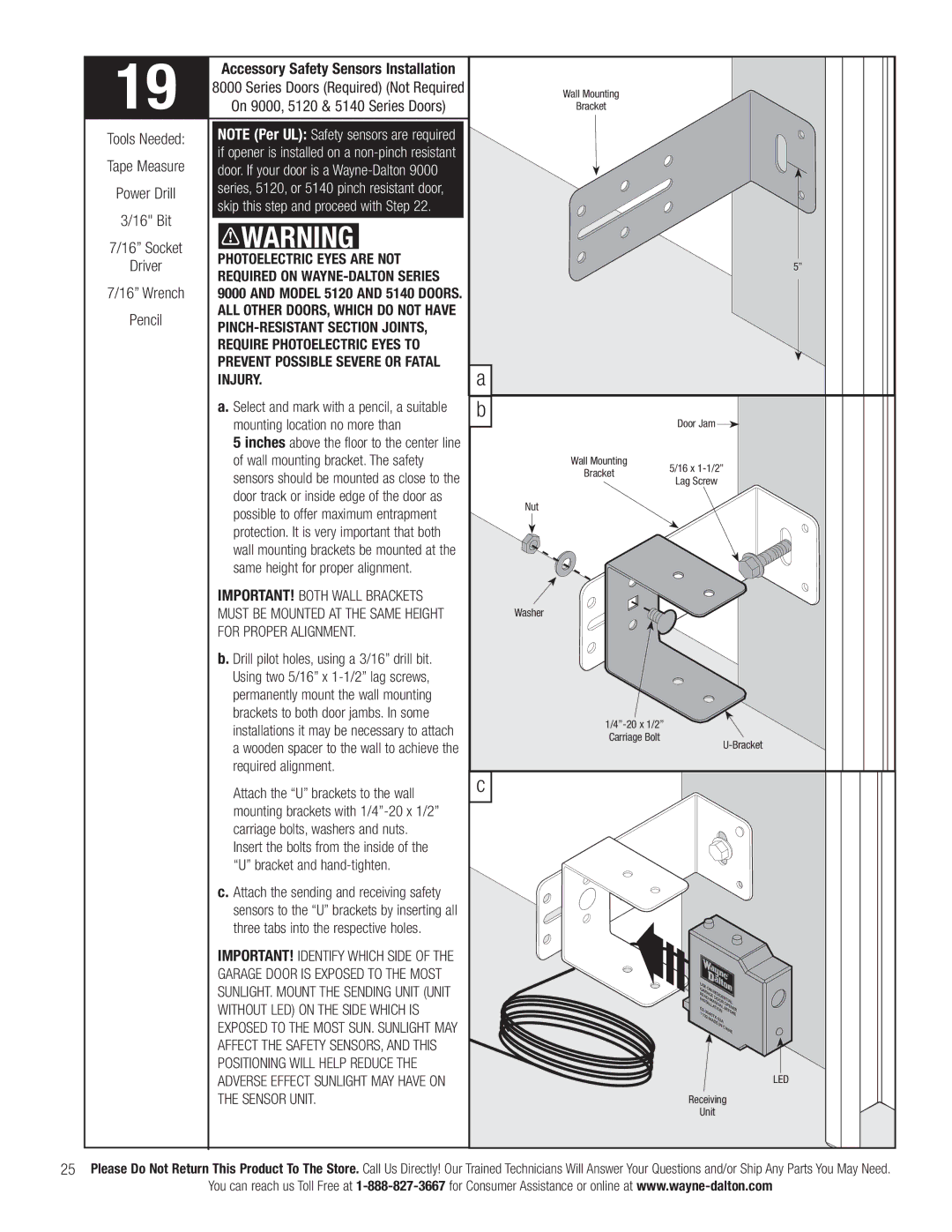
| a. Select and mark with a pencil, a suitable | b |
|
| mounting location no more than |
| Door Jam |
| 5 inches above the floor to the center line |
|
|
| of wall mounting bracket. The safety | Wall Mounting | 5/16 x |
| sensors should be mounted as close to the | Bracket | |
| Lag Screw | ||
|
| ||
| door track or inside edge of the door as | Nut |
|
| possible to offer maximum entrapment |
| |
|
|
| |
| protection. It is very important that both |
|
|
| wall mounting brackets be mounted at the |
|
|
| same height for proper alignment. |
|
|
IMPORTANT! BOTH WALL BRACKETS |
| |
MUST BE MOUNTED AT THE SAME HEIGHT | Washer | |
FOR PROPER ALIGNMENT. |
| |
b. Drill pilot holes, using a 3/16” drill bit. |
| |
Using two 5/16” x |
| |
permanently mount the wall mounting |
| |
brackets to both door jambs. In some | ||
installations it may be necessary to attach | ||
Carriage Bolt | ||
a wooden spacer to the wall to achieve the | ||
required alignment. | c | |
Attach the “U” brackets to the wall | ||
| ||
mounting brackets with |
| |
carriage bolts, washers and nuts. |
| |
Insert the bolts from the inside of the |
| |
“U” bracket and |
| |
c. Attach the sending and receiving safety |
| |
sensors to the “U” brackets by inserting all |
| |
three tabs into the respective holes. |
| |
IMPORTANT! IDENTIFY WHICH SIDE OF THE |
| |
GARAGE DOOR IS EXPOSED TO THE MOST |
| |
SUNLIGHT. MOUNT THE SENDING UNIT (UNIT |
| |
WITHOUT LED) ON THE SIDE WHICH IS |
| |
EXPOSED TO THE MOST SUN. SUNLIGHT MAY |
| |
AFFECT THE SAFETY SENSORS, AND THIS |
| |
POSITIONING WILL HELP REDUCE THE |
| |
ADVERSE EFFECT SUNLIGHT MAY HAVE ON | LED | |
THE SENSOR UNIT. | Receiving | |
| Unit |
25Please Do Not Return This Product To The Store. Call Us Directly! Our Trained Technicians Will Answer Your Questions and/or Ship Any Parts You May Need.
You can reach us Toll Free at