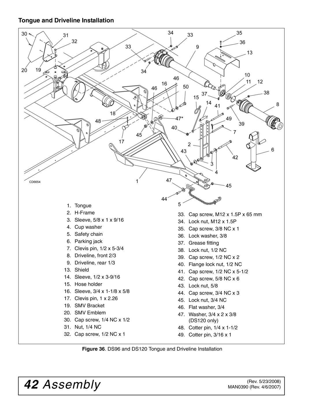
Tongue and Driveline Installation
|
|
|
|
|
| 1. | Tongue |
|
|
| 2. | 33. | Cap screw, M12 x 1.5P x 65 mm | |
| 3. | Sleeve, 5/8 x 1 x 9/16 | ||
| 34. | Lock nut, M12 x 1.5P | ||
| 4. | Cup washer | ||
| 35. | Cap screw, 3/8 NC x 1 | ||
| 5. | Safety chain | ||
| 36. | Lock washer, 3/8 | ||
| 6. | Parking jack | ||
| 37. | Grease fitting | ||
| 7. | Clevis pin, 1/2 x | ||
| 38. | Lock nut, 1/2 NC | ||
| 8. | Driveline, front 2/3 | ||
| 39. | Cap screw, 1/2 NC x 2 | ||
| 9. | Driveline, rear 1/3 | ||
| 40. | Flange lock nut, 1/2 NC | ||
| 13. | Shield | ||
| 41. | Cap screw, 1/2 NC x | ||
| 14. | Sleeve, 1/2 x | ||
| 42. | Cap screw, 5/8 NC x 6 | ||
| 15. | Hose holder | ||
| 43. | Lock nut, 5/8 | ||
| 16. | Sleeve, 3/4 x | ||
| 44. | Cap screw, 3/4 NC x 3 | ||
| 17. | Clevis pin, 1 x 2.26 | ||
| 45. | Lock nut, 3/4 NC | ||
| 19. | SMV Bracket | ||
| 46. | Flat washer, 3/4 | ||
| 20. | SMV Emblem | ||
| 47. | Washer, 3/4 x 2 x 3/8 | ||
| 30. | Cap screw, 1/4 NC x 1/2 | ||
|
| (DS120 only) | ||
| 31. | Nut, 1/4 NC | 48. | Cotter pin, 1/4 x |
| 32. | Cap screw, 1/2 NC x 1 | 49. | Cotter pin, 3/16 x 1 |
|
|
|
|
|
|
|
|
|
|
Figure 36. DS96 and DS120 Tongue and Driveline Installation
42Assembly
(Rev. 5/23/2008) MAN0390 (Rev. 4/6/2007)