Install Hydraulic Hose
On
NOTICE
■If using a cylinder other than the one supplied by Woods, make sure a breather fitting is installed
in the cylinder rod end port. Use a restricter fitting in the base end port to dampen the cutter lowering action.
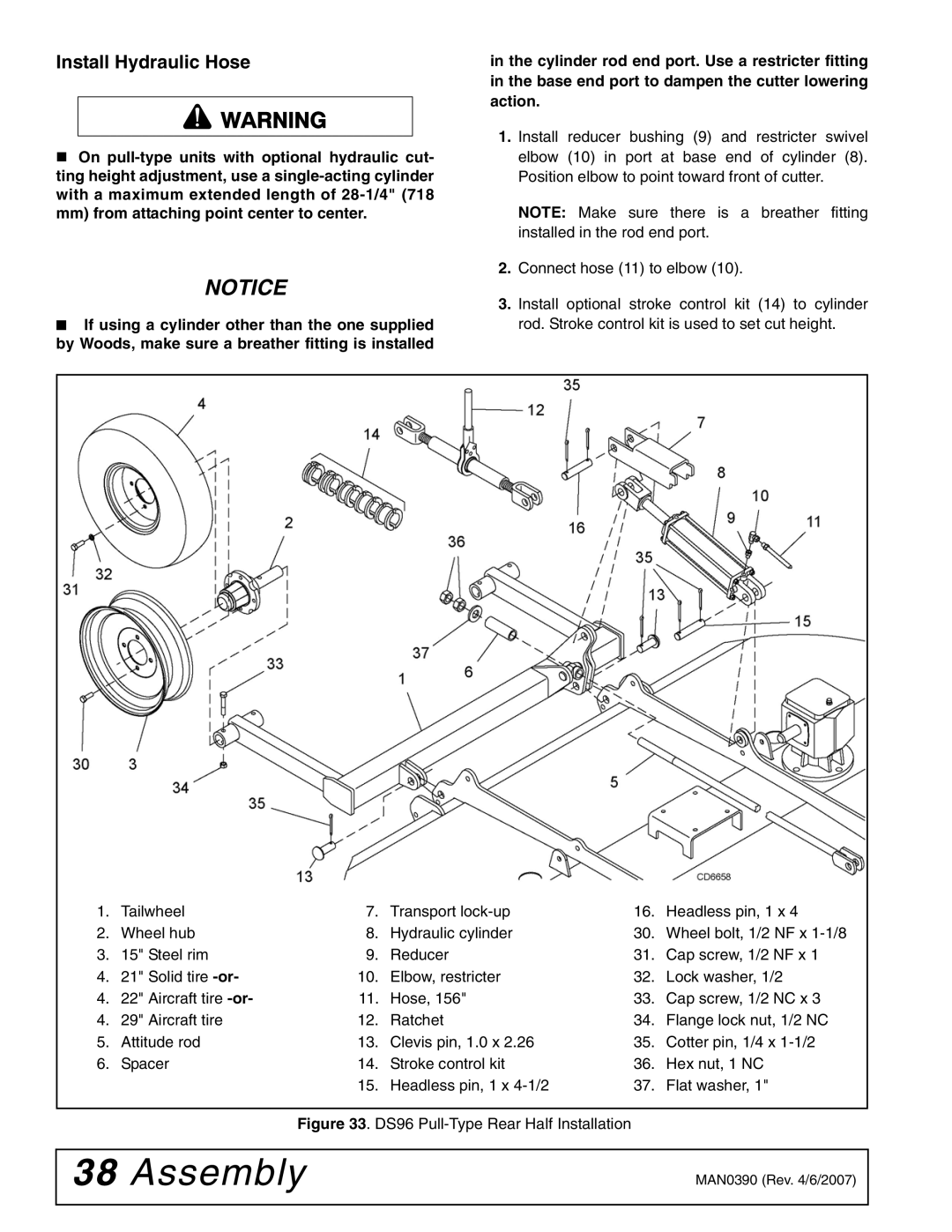
1.Install reducer bushing (9) and restricter swivel elbow (10) in port at base end of cylinder (8). Position elbow to point toward front of cutter.
NOTE: Make sure there is a breather fitting installed in the rod end port.
2.Connect hose (11) to elbow (10).
3.Install optional stroke control kit (14) to cylinder rod. Stroke control kit is used to set cut height.
1. | Tailwheel | 7. | Transport | 16. | Headless pin, 1 x 4 |
2. | Wheel hub | 8. | Hydraulic cylinder | 30. | Wheel bolt, 1/2 NF x |
3. | 15" Steel rim | 9. | Reducer | 31. | Cap screw, 1/2 NF x 1 |
4. | 21" Solid tire | 10. | Elbow, restricter | 32. | Lock washer, 1/2 |
4. | 22" Aircraft tire | 11. | Hose, 156" | 33. | Cap screw, 1/2 NC x 3 |
4. | 29" Aircraft tire | 12. | Ratchet | 34. | Flange lock nut, 1/2 NC |
5. | Attitude rod | 13. | Clevis pin, 1.0 x 2.26 | 35. | Cotter pin, 1/4 x |
6. | Spacer | 14. | Stroke control kit | 36. | Hex nut, 1 NC |
|
| 15. | Headless pin, 1 x | 37. | Flat washer, 1" |
Figure 33. DS96 Pull-Type Rear Half Installation
38 Assembly | MAN0390 (Rev. 4/6/2007) |
|
|