ASSEMBLE - DS120 MOUNTED CUTTER
Refer to Figure 42.
Place jackstands under cutter to raise it off the ground to provide clearance when assembling cutter. See “BLOCKING METHOD” on page 21 for jackstand placement.
Install A-Frame
1.Attach front
2.Attach, rear
3.Attach the two rear
4.Place both break links (7) together and position between front hole of rear
5.Place spacer sleeve (6) through front holes of break links. Align break links with bottom holes on front
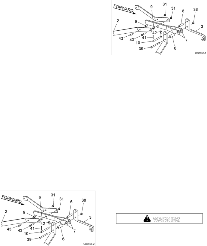
Category 2 Standard Hitch (Figure 40)
Install top link pin (10) and sleeve (6) into top holes of
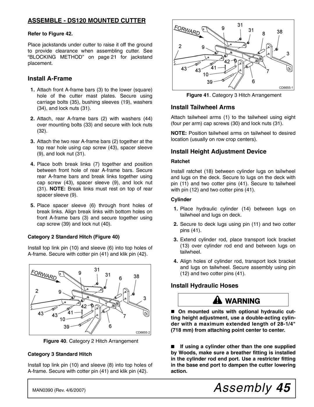
Figure 41. Category 3 Hitch Arrangement
Install Tailwheel Arms
Attach tailwheel arms (1) to the tailwheel using eight (four per arm) cap screws (30) and lock nuts (31).
NOTE: Position tailwheel arms on tailwheel to desired location (usually on row crop centers).
Install Height Adjustment Device
Ratchet
Install ratchet (18) between cylinder lugs on tailwheel and lugs on the deck. Secure to lugs on the deck with pin (11) and two cotter pins (41). Secure to tailwheel with pin (12) and two cotter pins (41).
Cylinder
1.Place hydraulic cylinder (14) between lugs on tailwheel and lugs on deck.
2.Secure to deck lugs using pin (11) and two cotter pins (41).
3.Extend cylinder rod, place transport lock bracket
(13)over cylinder rod end and between lugs on tailwheel.
4.Align holes of cylinder rod, transport lock bracket and lugs on tailwheel. Secure assembly using pin
(12)and two cotter pins (41).
Install Hydraulic Hoses
On mounted units with optional hydraulic cut- ting height adjustment, use a
Figure 40. Category 2 Hitch Arrangement
Category 3 Standard Hitch
Install top link pin (10) and sleeve (8) into top holes of
■If using a cylinder other than the one supplied by Woods, make sure a breather fitting is installed in the cylinder rod end port. Use a restricter fitting in the base end port to dampen the cutter lowering action.
MAN0390 (Rev. 4/6/2007) | Assembly 45 |
|
|