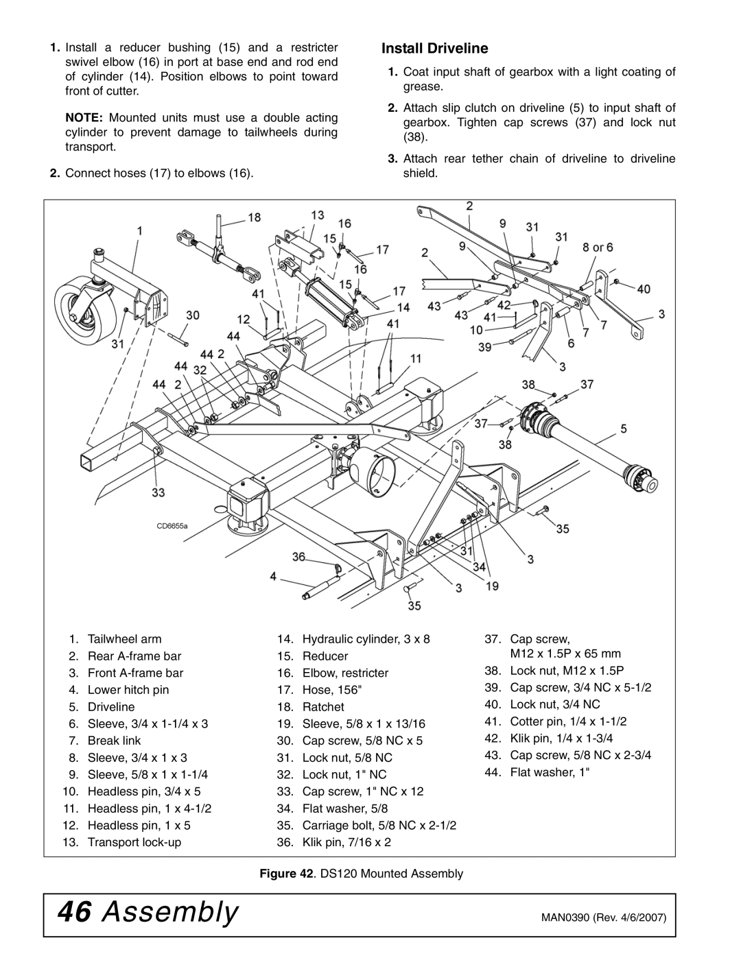
1.Install a reducer bushing (15) and a restricter swivel elbow (16) in port at base end and rod end of cylinder (14). Position elbows to point toward front of cutter.
NOTE: Mounted units must use a double acting cylinder to prevent damage to tailwheels during transport.
2.Connect hoses (17) to elbows (16).
Install Driveline
1.Coat input shaft of gearbox with a light coating of grease.
2.Attach slip clutch on driveline (5) to input shaft of gearbox. Tighten cap screws (37) and lock nut (38).
3.Attach rear tether chain of driveline to driveline shield.
1. | Tailwheel arm | 14. | Hydraulic cylinder, 3 x 8 | 37. | Cap screw, |
2. | Rear | 15. | Reducer |
| M12 x 1.5P x 65 mm |
3. | Front | 16. | Elbow, restricter | 38. | Lock nut, M12 x 1.5P |
4. | Lower hitch pin | 17. | Hose, 156" | 39. | Cap screw, 3/4 NC x |
5. | Driveline | 18. | Ratchet | 40. | Lock nut, 3/4 NC |
6. | Sleeve, 3/4 x | 19. | Sleeve, 5/8 x 1 x 13/16 | 41. | Cotter pin, 1/4 x |
7. | Break link | 30. | Cap screw, 5/8 NC x 5 | 42. | Klik pin, 1/4 x |
8. | Sleeve, 3/4 x 1 x 3 | 31. | Lock nut, 5/8 NC | 43. | Cap screw, 5/8 NC x |
9. | Sleeve, 5/8 x 1 x | 32. | Lock nut, 1" NC | 44. | Flat washer, 1" |
10. | Headless pin, 3/4 x 5 | 33. | Cap screw, 1" NC x 12 |
|
|
11. | Headless pin, 1 x | 34. | Flat washer, 5/8 |
|
|
12. | Headless pin, 1 x 5 | 35. | Carriage bolt, 5/8 NC x |
|
|
13. | Transport | 36. | Klik pin, 7/16 x 2 |
|
|
|
|
|
|
|
|
Figure 42. DS120 Mounted Assembly
46 Assembly | MAN0390 (Rev. 4/6/2007) |
|
|