Step 5: Installing Additional Inverters
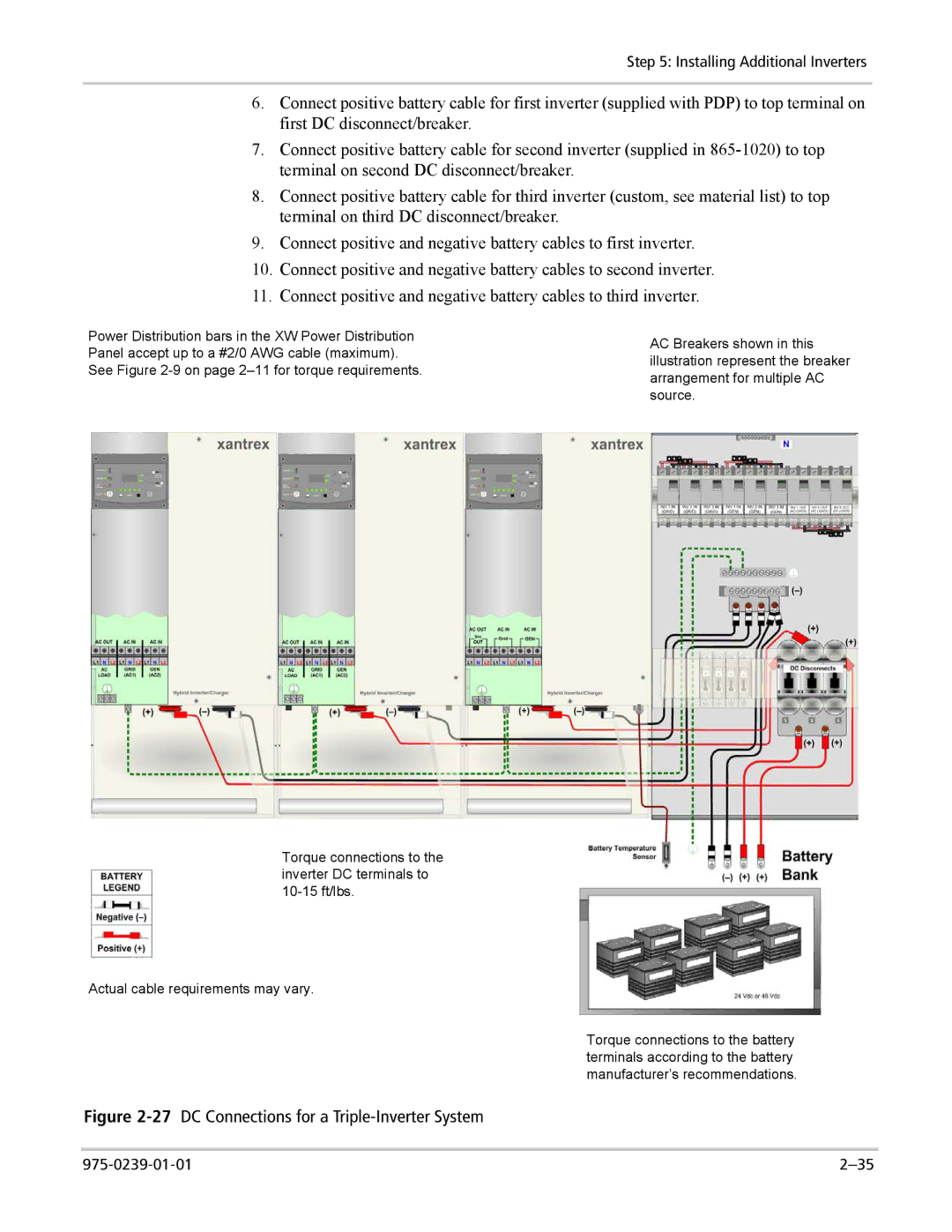
6.Connect positive battery cable for first inverter (supplied with PDP) to top terminal on first DC disconnect/breaker.
7.Connect positive battery cable for second inverter (supplied in
8.Connect positive battery cable for third inverter (custom, see material list) to top terminal on third DC disconnect/breaker.
9.Connect positive and negative battery cables to first inverter.
10.Connect positive and negative battery cables to second inverter.
11.Connect positive and negative battery cables to third inverter.
Power Distribution bars in the XW Power Distribution Panel accept up to a #2/0 AWG cable (maximum). See Figure
Torque connections to the inverter DC terminals to
Actual cable requirements may vary.
AC Breakers shown in this illustration represent the breaker arrangement for multiple AC source.
Torque connections to the battery terminals according to the battery manufacturer’s recommendations.
