Basic Functional Test - Single Inverter
AC Voltage Check
Important: This test requires the use of a voltmeter.
To perform an AC voltage check:
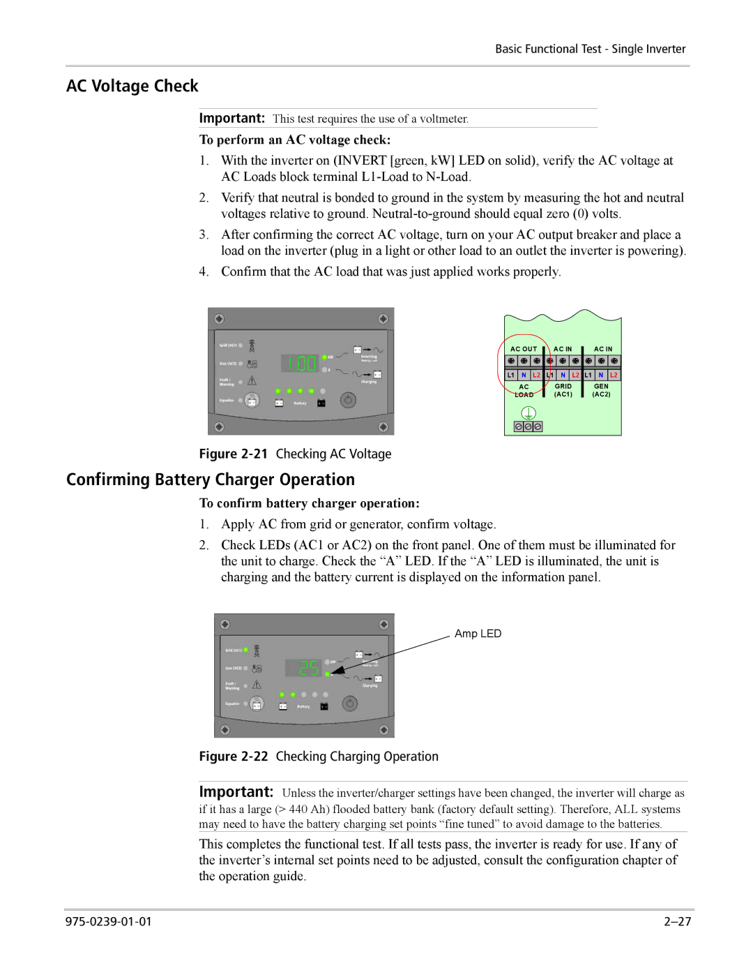
1.With the inverter on (INVERT [green, kW] LED on solid), verify the AC voltage at AC Loads block terminal
2.Verify that neutral is bonded to ground in the system by measuring the hot and neutral voltages relative to ground.
3.After confirming the correct AC voltage, turn on your AC output breaker and place a load on the inverter (plug in a light or other load to an outlet the inverter is powering).
4.Confirm that the AC load that was just applied works properly.
AC OUT | AC IN | AC IN |
|
|
|
L1 ![]() N
N ![]() L2
L2 ![]()
![]() N
N ![]() L2
L2 ![]() L1
L1 ![]() N
N ![]() L2
L2
AC | GRID | GEN | ||
|
|
| (AC1) | (AC2) |
|
|
|
|
|
|
|
|
|
|
|
|
|
|
|
|
|
|
|
|
Figure 2-21 Checking AC Voltage
Confirming Battery Charger Operation
To confirm battery charger operation:
1.Apply AC from grid or generator, confirm voltage.
2.Check LEDs (AC1 or AC2) on the front panel. One of them must be illuminated for the unit to charge. Check the “A” LED. If the “A” LED is illuminated, the unit is charging and the battery current is displayed on the information panel.
Amp LED
Figure 2-22 Checking Charging Operation
Important: Unless the inverter/charger settings have been changed, the inverter will charge as if it has a large (> 440 Ah) flooded battery bank (factory default setting). Therefore, ALL systems may need to have the battery charging set points “fine tuned” to avoid damage to the batteries.
This completes the functional test. If all tests pass, the inverter is ready for use. If any of the inverter’s internal set points need to be adjusted, consult the configuration chapter of the operation guide.
