Inverter/Charger Installation
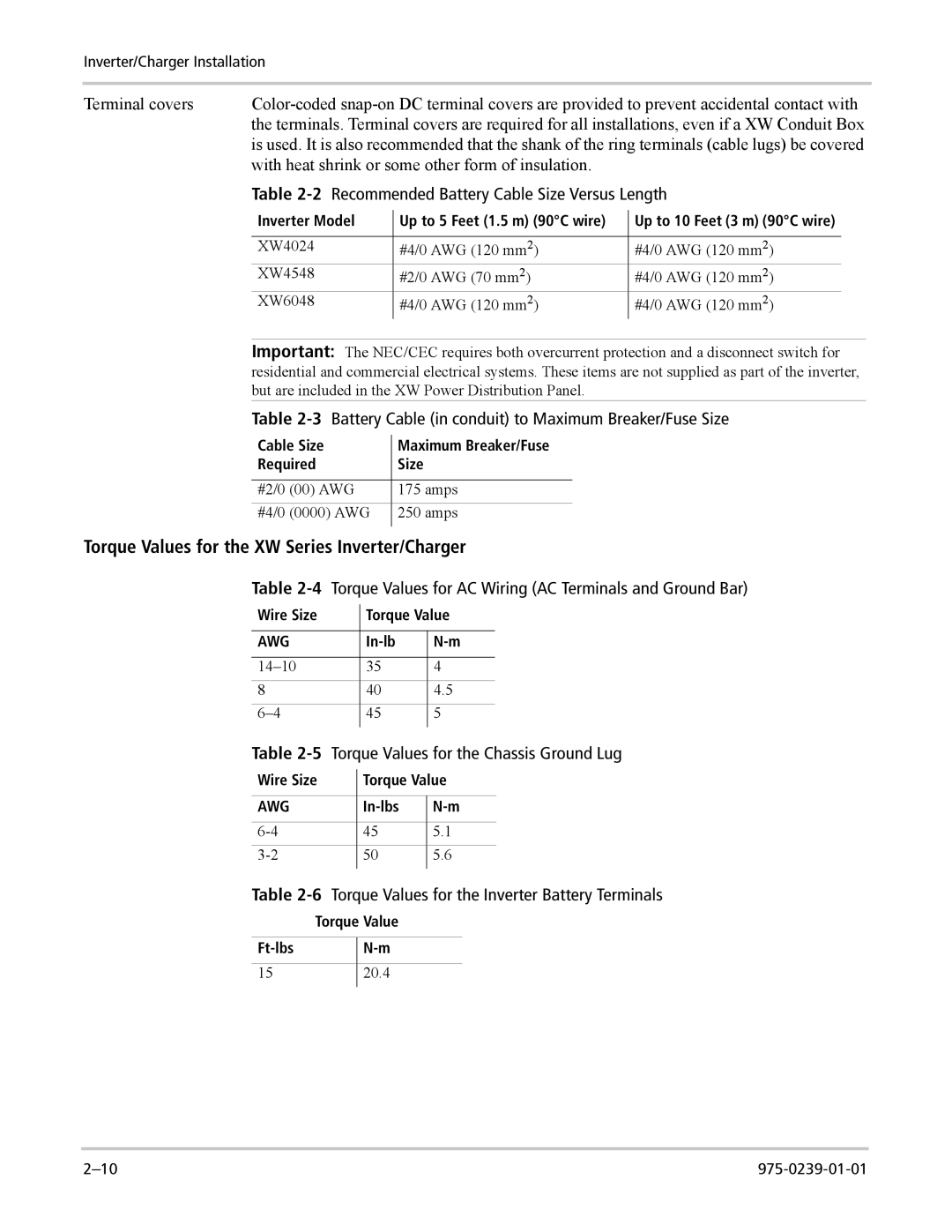
Terminal covers | ||||||
| the terminals. Terminal covers are required for all installations, even if a XW Conduit Box | |||||
| is used. It is also recommended that the shank of the ring terminals (cable lugs) be covered | |||||
| with heat shrink or some other form of insulation. |
|
|
| ||
| Table | |||||
| Inverter Model |
| Up to 5 Feet (1.5 m) (90°C wire) |
| Up to 10 Feet (3 m) (90°C wire) | |
|
|
| ||||
|
|
|
|
|
| |
| XW4024 |
| #4/0 AWG (120 mm2) |
| #4/0 AWG (120 mm2) |
|
| XW4548 |
| #2/0 AWG (70 mm2) |
| #4/0 AWG (120 mm2) |
|
| XW6048 |
| #4/0 AWG (120 mm2) |
| #4/0 AWG (120 mm2) |
|
Important: The NEC/CEC requires both overcurrent protection and a disconnect switch for residential and commercial electrical systems. These items are not supplied as part of the inverter, but are included in the XW Power Distribution Panel.
Table 2-3 Battery Cable (in conduit) to Maximum Breaker/Fuse Size
Cable Size | Maximum Breaker/Fuse | |
Required | Size | |
|
|
|
#2/0 | (00) AWG | 175 amps |
#4/0 | (0000) AWG | 250 amps |
|
|
|
Torque Values for the XW Series Inverter/Charger
Table | Torque Values for AC Wiring (AC Terminals and Ground Bar) | |||
Wire Size |
| Torque Value | ||
| ||||
|
|
|
|
|
AWG |
| |||
|
|
|
|
|
| 35 | 4 |
| |
8 |
| 40 | 4.5 |
|
| 45 | 5 |
| |
|
|
|
|
|
Table | Torque Values for the Chassis Ground Lug | |||
Wire Size |
| Torque Value | ||
| ||||
|
|
|
|
|
AWG |
| |||
|
|
|
|
|
| 45 | 5.1 |
| |
| 50 | 5.6 |
| |
|
|
|
|
|
Table | Torque Values for the Inverter Battery Terminals | ||
Torque Value | |||
|
|
|
|
| |||
|
|
|
|
15 |
| 20.4 |
|
|
|
|
|
