Zebra TTP
P1003636-002 TTP 7030 Technical Manual 10/05/2009
Contents
Programming
Interface
P1003636-002 TTP 7030 Technical Manual 10/05/2009
Introduction
About This Manual
Updating
Contacts
Subject line Emaillist
Product Presentation
Printer Exterior, Rear View
Printer Exterior, Side View
Indicators
Status Indicator
Control Board Indicators
Feed Button
Installation
Installation Considerations
Top view
Electrostatic Discharges, and Earth Currents
Ambient Light
Connecting To The Computer
Using a Serial Adapter
Connect the TTP
Fitting a serial adapter to the printer
Connecting the Power
GND
Is a power button available for the printer?
Making a Test Printout
Installing a Printer Driver
Paper Level Sensor Indicators on Roll Holder
Paper Level Sensors
Paper-near-end Sensor Connection
Operation
Installing a Paper Roll
Make sure the printer is turned on
Angle
Cut the paper in a suitable angle. See Figure
Clearing Paper Jams
Open the Print Module
Programming
Text text
How The Commands Are Described
Two-Byte Character Definitions
Therefore, the two-byte representation of 731 is
Summary Of Control Codes & Escape Sequences
50 n1 27 5 80 n1 Parameter-setting data Enquiry
27 5 Head temperature Enquiry
27 5 Bootware version Enquiry
27 5 Device ID Enquiry
Software Command Syntax
Black Mark Top-Of-Form Commands
Text Commands
Changes the alignment of text and logotypes
Left Center Right
Selects font
Selects normal font font ESC ! 4 selects font
Selects font ESC ! 5 selects font
Turns OFF Italics Normal Turns on Italics
ESC T n1 Reversed/Inversed Text
ESC w n1
Commands, are not cancelled
Overprint the O
ESC d n1 Make n Linefeeds
Barcode Commands
Samples of barcodes
Specifies the bar code field No -15. Bar code fields may be
Specified in any order
Add-on. Two of five characters are allowed of the add-on
But other values than 0 to 15 are ignored
N2 . . . nx Specifies bar code data bytes
Must be placed at the end of the bar code data
Error level, 0=auto, 1=Level0, 2=Level1, etc
Columns
Dot Height, sets mow many pixel lines each row consists
Graphics Commands
Determines the number of bytes. Range
ESCr000000000000001193000024003
ESC g n1 Print Logotype
Run presenter
Print Commands
Form feed Clear presenter
Print buffer full Press on FF-button
ESC j n1 Paper Reverse
To auto
Cut And Present Commands
You can also use RS together with the paper advance command
Gives a cut & eject after the last text line
Ejects the presented
Retracts the presented
ENQ
System Related Commands
Erases all logotypes stored in the flash Prom
Erases all fonts stored in the flash Prom
See Default Parameter Settings on
Set several parameters at once
Status Reporting Commands
Paper-near-end Enquiry
Send
Read
Sensor Status
Readn Where n can be ‘A’ Ascii or 41 hex or 65 dec
That is, a response with the value 129 indicates version
That is, a response with the value 130 indicates version
Under Summary Of Parameter Settings on
One-byte marker. Range 1h to 255h
Font Loading
File Format
Character bitmap data
Logotypes
Loading
All logotypes are erased with the ESC&L command
Printing
Status Reporting
Default Parameter Settings
Programming
Default Parameter Settings
Default Value
Summary Of Parameter Settings
Serial Interface Set-Up
Xon / Xoff
Select what handshaking to use on the serial interface
No flow control
Hardware
Parallel Port Setup
No, paper out and error signals are not disabled
Yes, paper out and error signals are disabled
Current consumption
Print Setup
Disable the loop
Cm loop
Burn pulse
Controls what the printer does with buffered data
Burn pulse + history
Burn pulses + history
LF = Ignored
Black mark synchronization enabled
CR = Ignored
On the paper
Fixed Document Mode. Shorter documents will automatically
Contents printouts shorter than the value specified by
Determines what should control the page length
Be extended, while longer documents will be divided into
Fixed Document Mode
Length P37 P38
Feeds 50 mm between black mark and cut
Sets max black mark length to 5 mm
Sets min black mark length to 4 mm
Add 30-mm top margin
Do nothing when new page is printed. Auto-eject and retract
Eject page when new page is printed. Retract disabled
Retract page when new page is printed
Will be retracted. Range 1-30, 1 step = 10 s
No indication
Off
Automatic Distance Calculation
Paper Near End indication
Default Parameter Settings
Setup
Printable Area
N43 N44
Aligning Preprint And Thermal Print
Recommended black mark size and position
Setup
Enables/disables black mark check
Parameters Used
Garbage, Black Mark and Out of Paper Detection
Parameter n41 and n42 -Black Mark Cut Offset
Specified by the ESC x command
Send Text and graphics
Send RS Cuts and ejects the printout
Simple Calibration Process
Black-Mark Sensing from Within Windows
Interface
+ Data
Cable power
USB Interface
Cable ground
Setup Options
Serial Option, TTP
Interface
Maintenance
Fault Finding
Fault Finding
101
Cleaning The Print Head
Printer with retract
Fitting a Shutter
Firmware
Specifications
Print Data
None, Odd or Even
Command Code Modes Non-Windows Applications
Basic Character Set
108
109
Bar Codes Non-Windows Applications
Paper Handling
Printer Dimensions
Environmental Conditions
General
Paper Specification
Miscellaneous
Thermal coating
Perforation
Preprinting
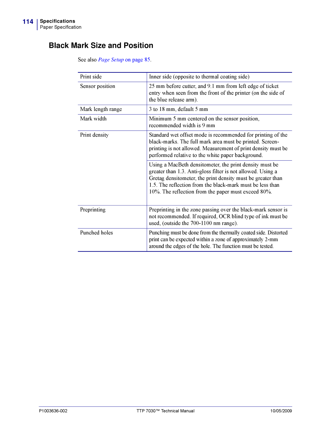
Black Mark Size and Position
Print can be expected within a zone of approximately 2-mm
Around the edges of the hole. The function must be tested
Accessories
Part Number List
Printers
116
117
Roll Holders
Roll Holder for Paper Rolls up to 150 mm
119
120
中国 RoHS 材料声明 China RoHS Material Declaration
表示该部件的某一均质材料中的有毒有害物质的含量超出 SJ/Txxx-2006标准规定的限量要求。
122
Index
Numerics
Index
Index
Connector Port
USB
Page
Zebra Technologies Europe Limited