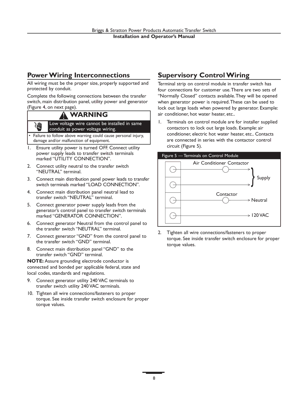
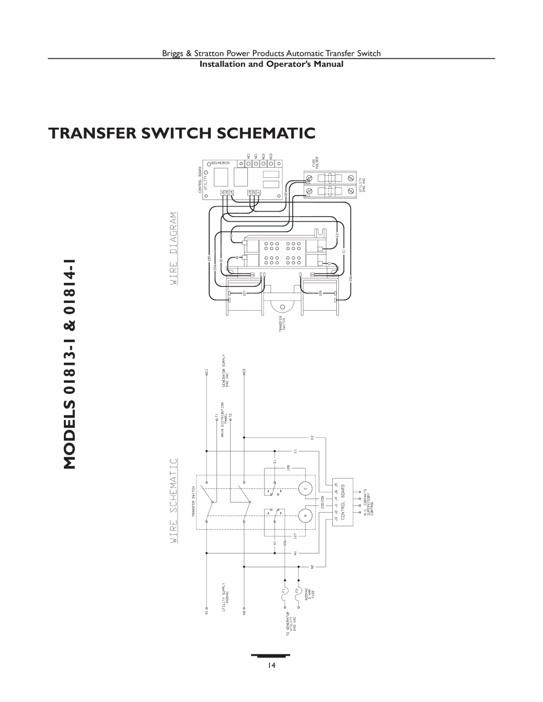
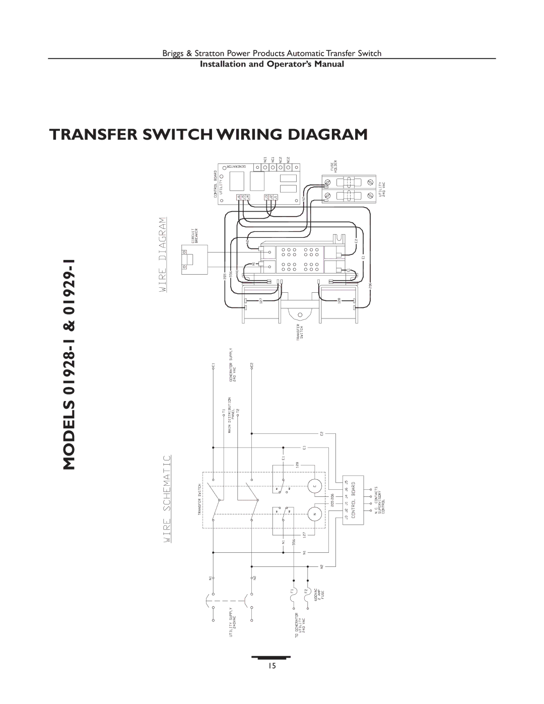
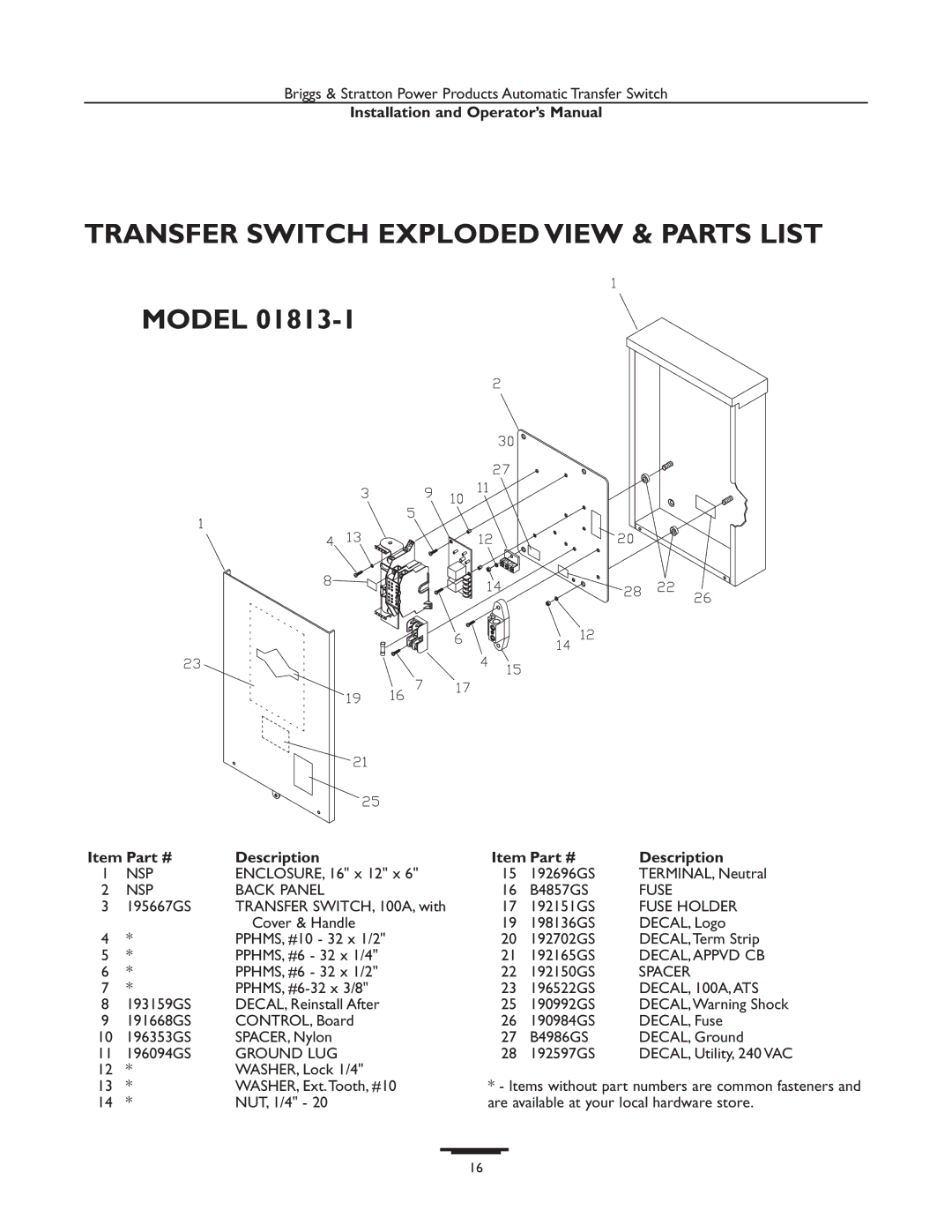
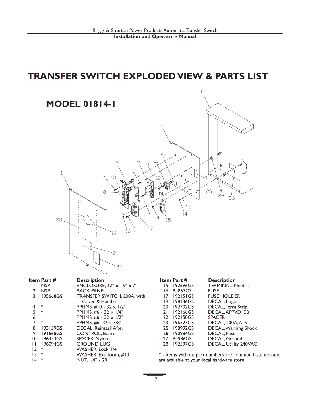
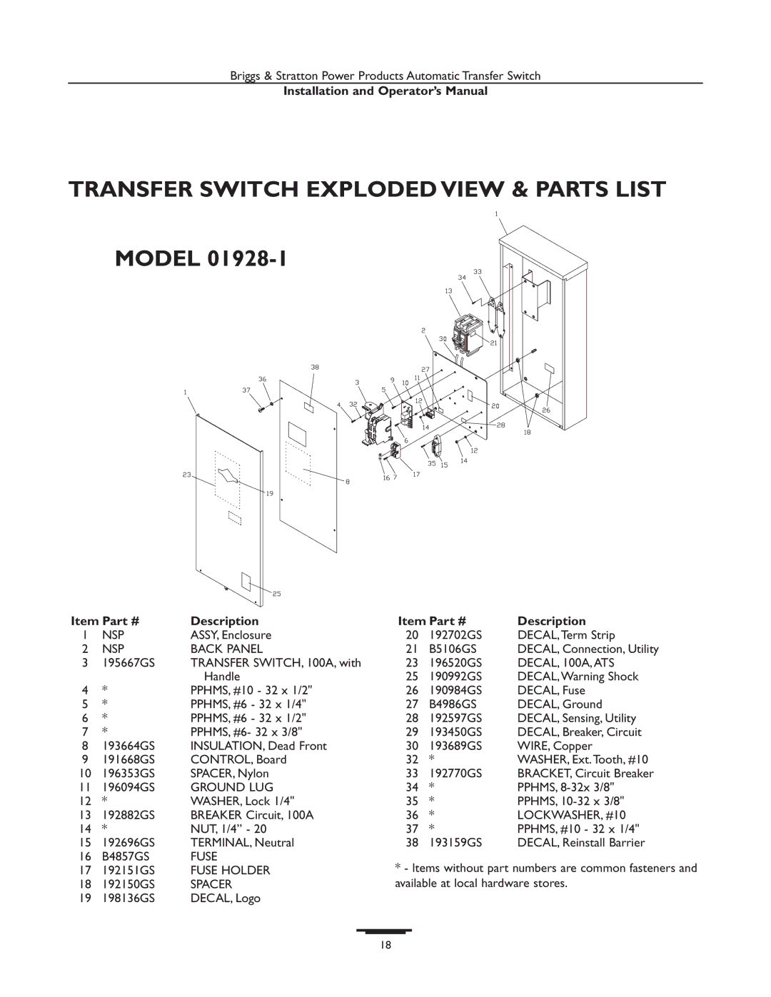
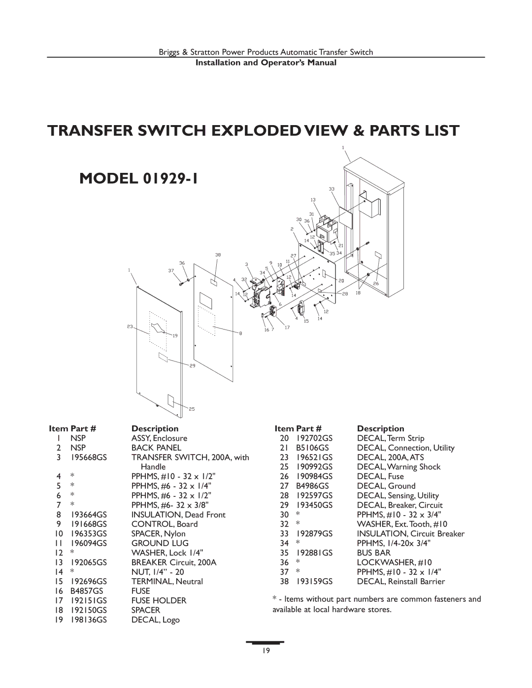
Briggs & Stratton 01928-1, 01814-1 manual Transfer Switch Exploded View & Parts List, Description

Page 16

Briggs & Stratton Power Products Automatic Transfer Switch

Installation and Operator’s Manual

TRANSFER SWITCH EXPLODED VIEW & PARTS LIST

MODEL 01813-1

Item Part #

Description

Item Part #

Description

1

NSP

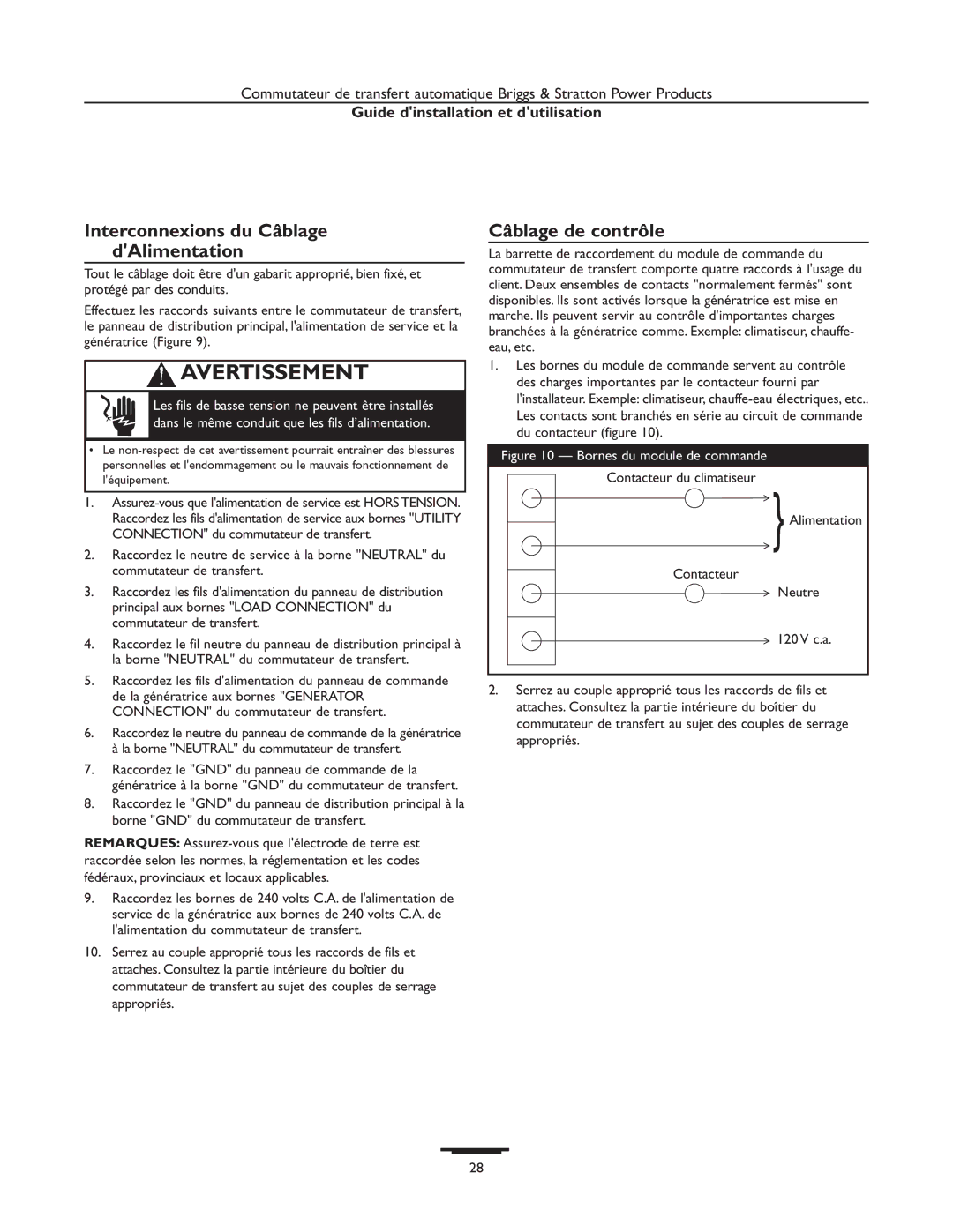
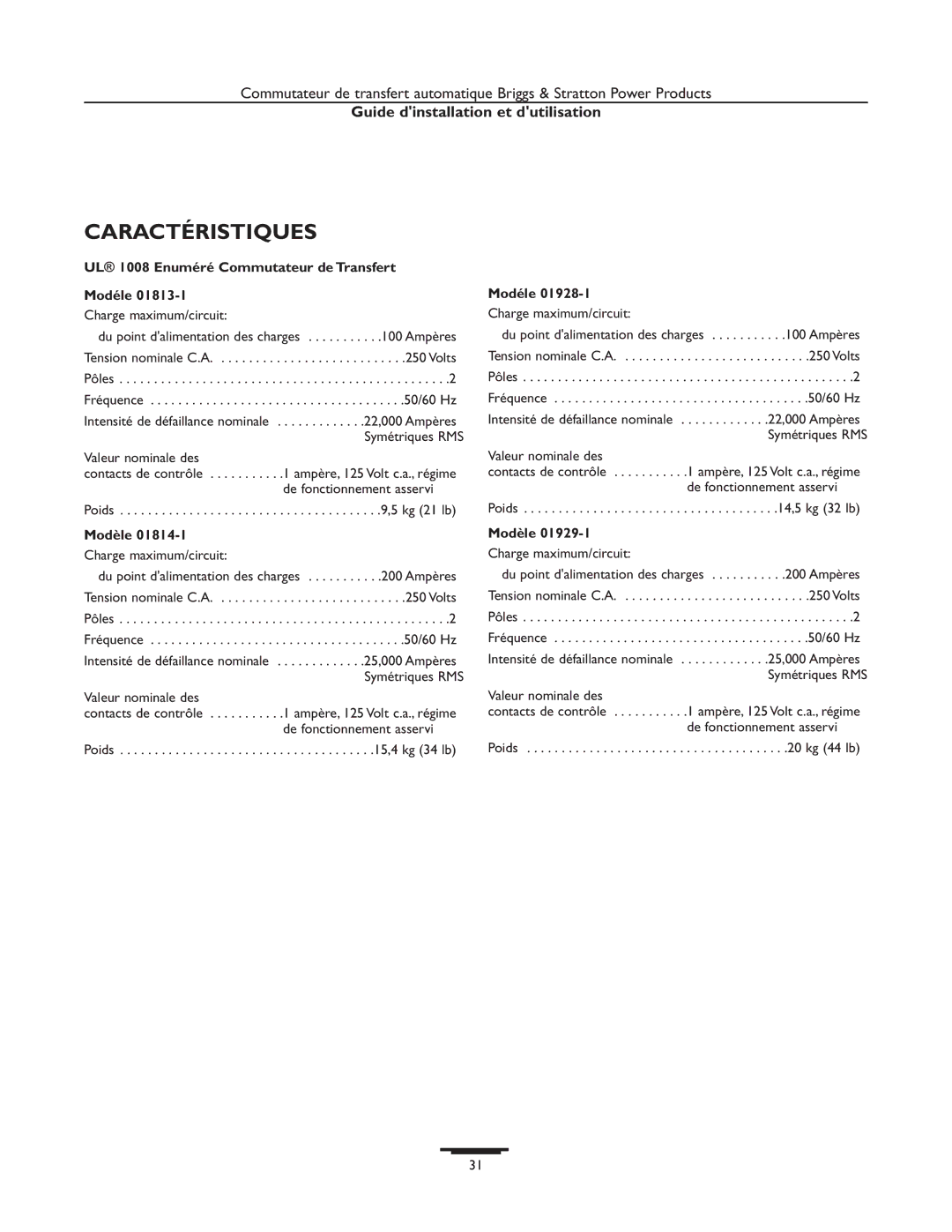
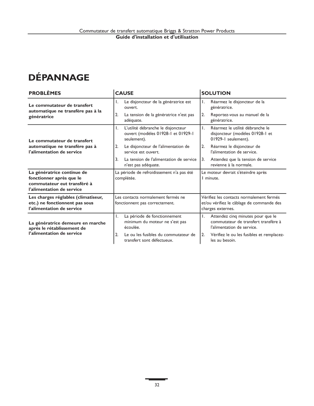
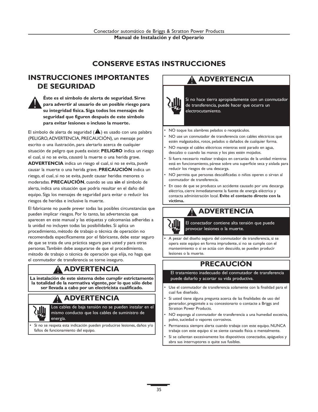
ENCLOSURE, 16" x 12" x 6"

15

192696GS

TERMINAL, Neutral

2

NSP

BACK PANEL

16

B4857GS

FUSE

3

195667GS

TRANSFER SWITCH, 100A, with

17

192151GS

FUSE HOLDER


Cover & Handle

19

198136GS

DECAL, Logo

4

*

PPHMS, #10 - 32 x 1/2"

20

192702GS

DECAL,Term Strip

5

*

PPHMS, #6 - 32 x 1/4"

21

192165GS

DECAL,APPVD CB

6

*

PPHMS, #6 - 32 x 1/2"

22

192150GS

SPACER

7

*

PPHMS, #6-32 x 3/8"

23

196522GS

DECAL, 100A,ATS

8

193159GS

DECAL, Reinstall After

25

190992GS

DECAL,Warning Shock

9

191668GS

CONTROL, Board

26

190984GS

DECAL, Fuse

10

196353GS

SPACER, Nylon

27

B4986GS

DECAL, Ground

11

196094GS

GROUND LUG

28

192597GS

DECAL, Utility, 240 VAC

12

*

WASHER, Lock 1/4"


13

*

WASHER, Ext.Tooth, #10

* - Items without part numbers are common fasteners and

14

*

NUT, 1/4" - 20

are available at your local hardware store.

16

Image 16
Contents Amp / 200 Amp Table of Contents Only qualified electricians should attempt installation Important Safety InstructionsUse transfer switch only for intended uses Introduction For the Home OwnerOwner Orientation Shipment Contents InstallationDelivery Inspection Typical Transfer Switch Mounting for Models 01928-1 Power Wiring Interconnections Typical Installation Diagram for Transfer Switch Testing the Automatic Transfer Switch System OperationUL 1008 Listed Transfer Switch Model SpecificationsFault Current Rating ,000 RMS Symmetrical Amperes Troubleshooting Problem Cause CorrectionInstallation and Operator’s Manual Transfer Switch Schematic Models 01813-1Transfer Switch Wiring Diagram Models 01928-1Description Transfer Switch Exploded View & Parts ListItems without part numbers are common fasteners DECAL, 200A,ATS LOCKWASHER, #10 BUS BAR Installation and Operator’s Manual Limited Warranty Guide dinstallation et dutilisation Table DES MatièresAvertissement Introduction Au Détaillant ou à lEntrepreneur Procédant à lInstallationAu Propriétaire Résidentiel Conseils au Propriétaire Responsabilités de lInstallateurDescription de lÉquipement Installation Consignes dinstallationDéballage Vérification de la LivraisonUne installation alternative du commutateur de transfert Interconnexions du Câblage dAlimentation Câblage de contrôleSchéma dInstallation Typique du Commutateur de Transfert Fonctionnement Mise À Lessai DU Commutateur DE Transfert AutomatiqueSéquence Automatique Si vous Devez Communiquer avec lUsineCaractéristiques UL 1008 Enuméré Commutateur de Transfert ModéleCharge maximum/circuit Valeur nominale desDépannage Garantie Limitée Tabla DE Contenido Manual de Instalación y del OperarioAdvertencia PrecauciónIntroducción Para el Propietario DomésticoOrientación para el Propietario Responsabilidades del InstaladorDescripción del Equipo Lea y cumpla las instrucciones incluidas en el manualInstalación DesempaquePautas de Montaje Inspección al Momento de la EntregaFigura 13 Montaje de un Conectador Alternativo Cableado de Control de Supervisión Interconexiones de Cableado de EnergíaContactor del Acondicionador de aire Alimentación Neutro Figura 11 Un Esquema Típico de Instalación para Conectador Sistema Funcionamiento Prueba DEL Conectador AutomáticoSecuencia Automática Si Necesita Llamar a FábricaEspecificaciones Problemo Causa AccionReparacion DE Averias Garantía Limitada