|
| 25 |
|
| TIGHTEN! |
| 67 | 5 |
65 | 66 |
|
69 |
|
|
92 |
| |
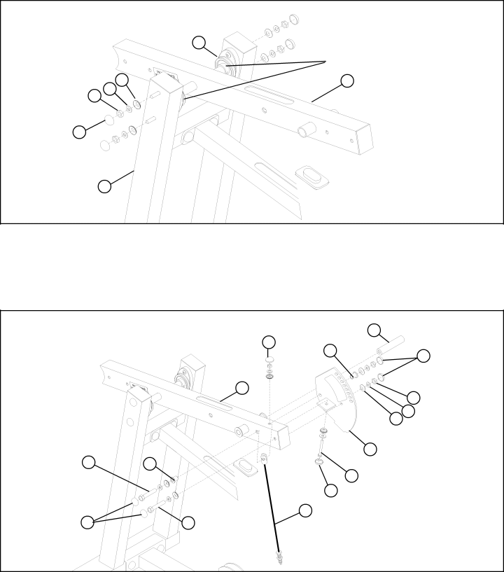
FIGURE 26 |
|
|
STEP 26:
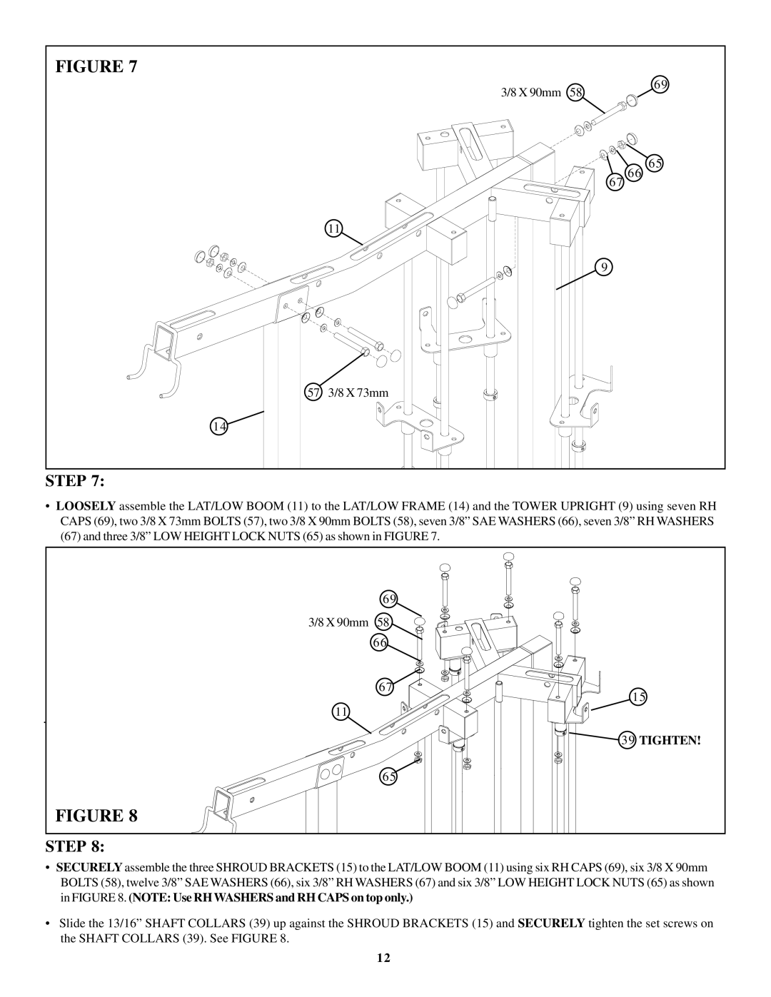
•SECURELY assemble the PIVOTARM (5) to the LEG CURL/EXT FRAME (92) using four previously inserted 3/8 X 76mm BUTTON HEAD BOLTS (63), four RH WASHERS (67), four 3/8” SAE WASHERS (66), four 3/8” LOW HEIGHT LOCK NUTS (65) and four RH CAPS (69) as shown in FIGURE 26.
•IMPORTANT! When PIVOT ARM (5) is centered and level in the PILLOW BLOCKS (25), tighten the PILLOW BLOCK set screws.
| 69 | 83 |
|
| |
| 44 | 68 BLACK |
|
| |
| 5 | 65 |
|
| |
|
| 67 66 |
|
| 20 |
3/8 X 73mm 57 | 48 |
|
|
| 58 3/8 X 90mm |
| 68 BLACK | |
69 | 73 |
|
55 3/8 X67mm |
| |
FIGURE 27 |
|
|
STEP 27:
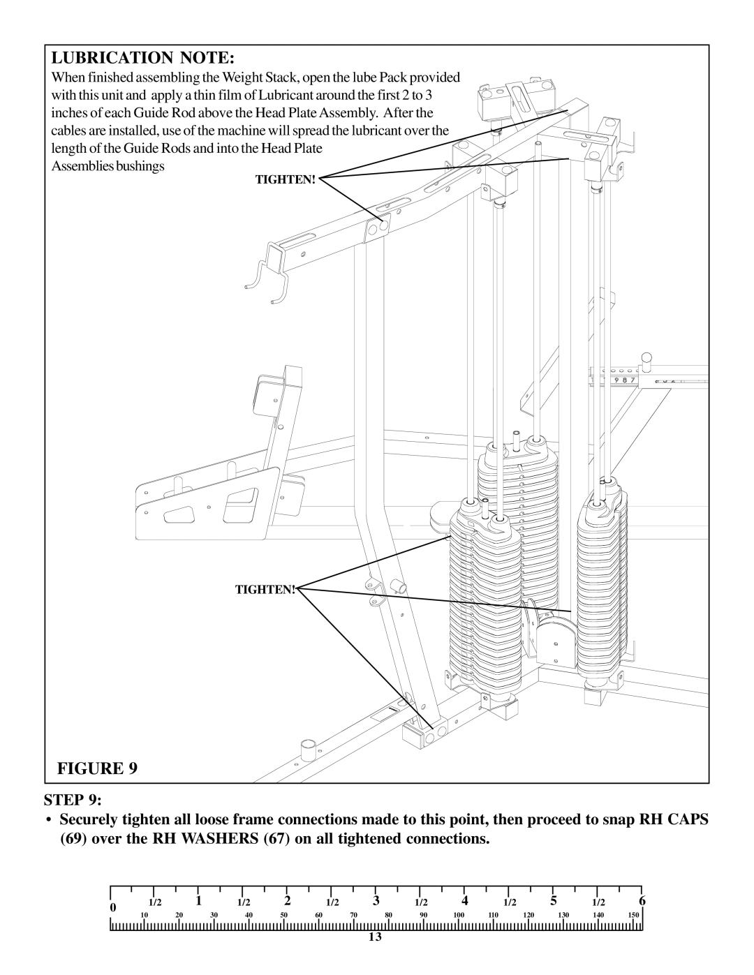
•SECURELY assemble the MULTI PRESS ADJUST PLATE (20) to the PIVOT ARM (5) using three RH CAPS (69), three BLACK RH CAPS (68), one 3/8 X 67mm BOLTS (55), one 3/8 X 73mm BOLT (57), one 3/8 X 90mm BOLT (58), six 3/8” SAE WASH- ERS (66), six 3/8” RH WASHERS (67), one 3/8 X 3/4” FLANGE SPACER (48), one 3/8 X 1” FLANGE SPACER (44), one MULTI PRESS CABLE (73) and three 3/8” LOW HEIGHT LOCK NUTS (65) as shown in FIGURE 27. (NOTE:Assemble the MULTI PRESS
CABLE to the second set of holes.)
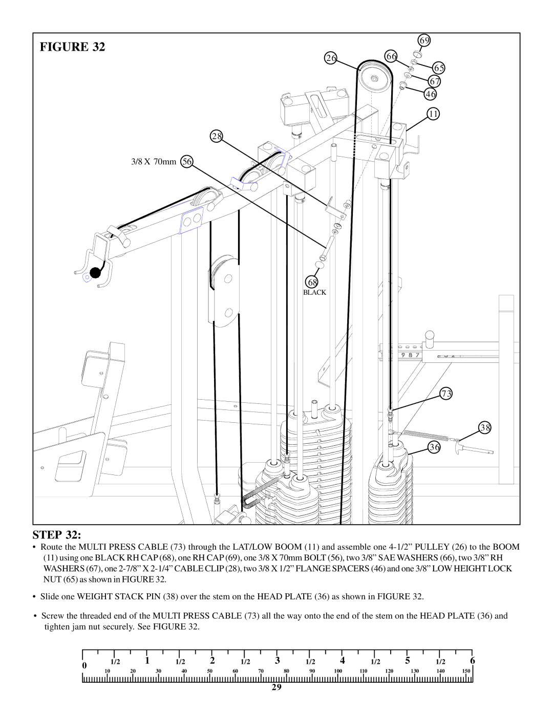
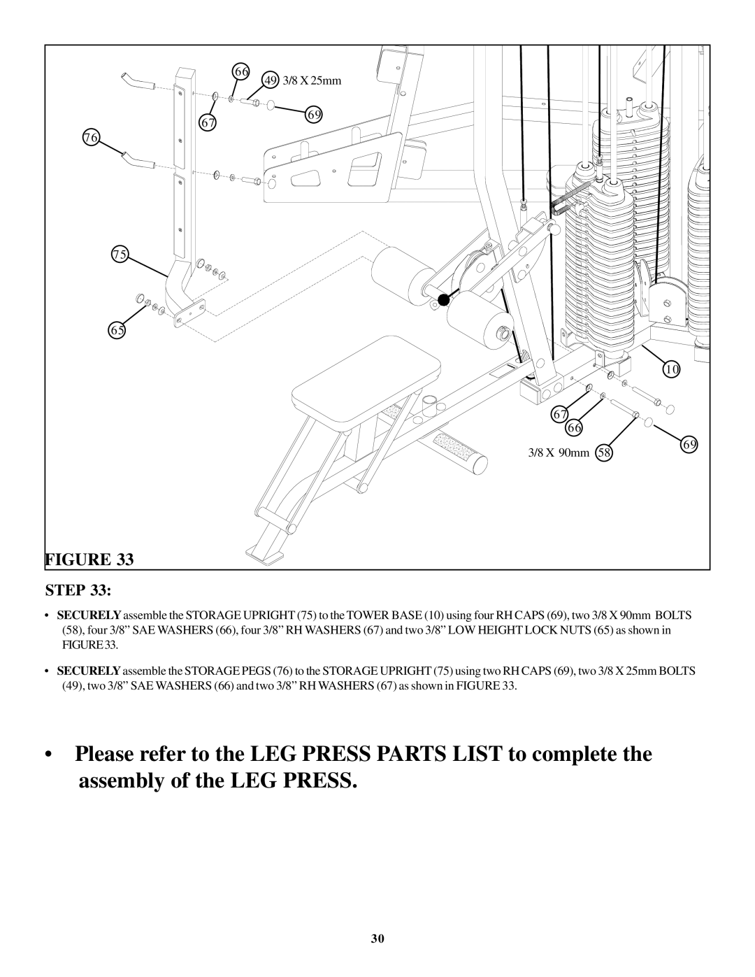
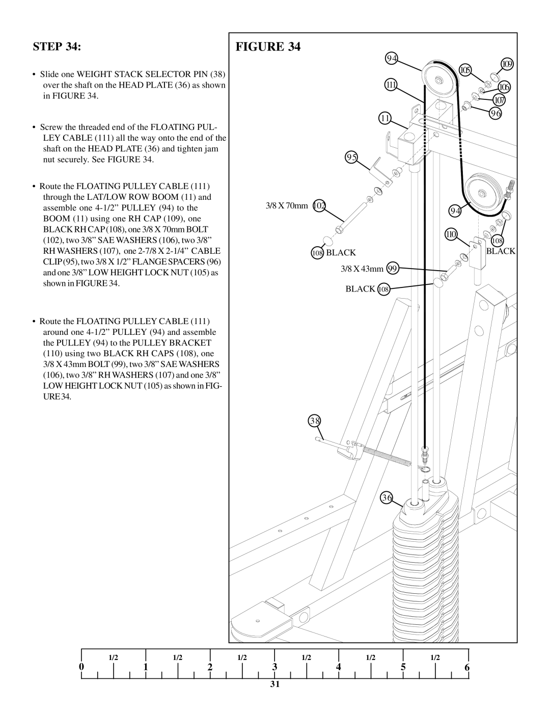
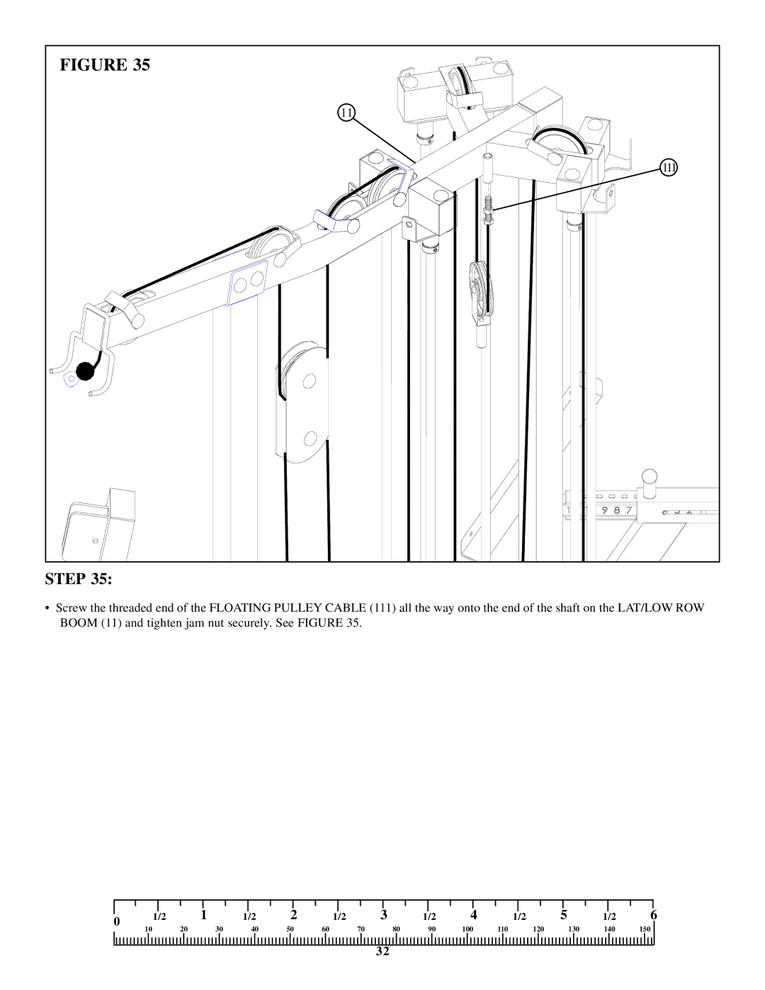
•Insert one
24
