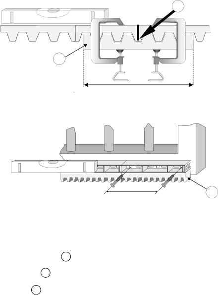
Centurion CP72SR5 installation manual 200mm

Page 14

59

58

200 - 300mm

LEVEL

200mm

60

MOUNTING RACK CONTINUED

-A simple way of ensuring correct pitch spacing when joining steel rack is to clamp a small offcut 58 between the two pieces.

-Check that weld 59 does not foul with meshing surfaces.

-If RAZ ™ rack 60 is used, then start installing from the right hand side of the gate working towards the LHS. Use fastening screws e.g. “TEK” screws at least every 200mm.

12

Image 14
Contents Sliding Gate Automation Page Oil Specifications Grade 75W90 Qty 75ml Major Components Typical D5 ShownStart kgF RUN kgF Gate Mass kg 300 500 ANTI-LIFT Brackets Duty Cycle Curves Recommended Installation and Cable Thickness REQUIREMENTS† Mechanical Mounting Details Option 1 Bolt down onto concrete plinthPage Option 2 Set into concrete plinth Provision for Cables Gearbox Mounting Down Details Mounting Rack Useful TIP200mm Installing Chain Drive Systems Setting Mechanical Clutch A5 only Ensure fan has stopped turningMounting Configuration For Steel Rack Mounting of Gate SensorPower Wiring see page 15 for Signal Wiring Removable ConnectorsSignal Wiring CP80 and CP81 Recommended Lightning Protection Commissioning Block Diagram Setting Motor Direction Gate Closes Towards Left Above Black Blue RED Towards RightSelecting Programme Mode Setting Gate Limits A5 onlySetting Gate Limits Start Automated Gate Limits RoutineD3/D5 Motor Automatic SET-UP Exit Gate Limits Routine D3/D5 only Start Manual Gate Limits RoutineAlign Origin Switch A5 Motor Manual SET-UPExit Gate Limits Routine A5 only Functions SelectFactory Defaults Highlighted Timer and Counter Setting Main Unit Menu Measure Procedure to Programme Controller Back to Factory Settings Fault Finders Guide D3 / D5 OperatorsGate Opens to Pedestrian and Closes Page Centurion