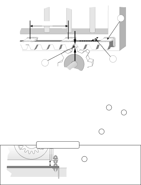
Centurion CP72SR5 installation manual Mounting Rack, Useful TIP

Page 13

55

±300 mm

56

57

MOUNTING RACK

-Attach steel rack to gate using 25x25x2mm angle brackets 55 . Distance between centerline of rack and edge of gate should be 20mm (see 56 ).

-For best results support rack every 300mm.

-Rack must be mounted level with a 2 - 3mm clearance 57 .

USEFUL TIP

λ Raise gearbox by an additional 3mm.

λ P u t g e a r b o x i n t o m a n u a l m o d e (see 37 on page 22)

λ Mesh rack and pinion fully and mount rack.

Slide gate backwards and forwards ensuring that rack mesh is smooth and never tight.

λ Drop gearbox by 3mm to create 3mm tooth clearance.

11

Image 13
Contents Sliding Gate Automation Page Major Components Typical D5 Shown Oil Specifications Grade 75W90 Qty 75mlStart kgF RUN kgF Gate Mass kg 300 500 ANTI-LIFT Brackets Duty Cycle Curves Recommended Installation and Cable Thickness REQUIREMENTS† Option 1 Bolt down onto concrete plinth Mechanical Mounting DetailsPage Option 2 Set into concrete plinth Provision for Cables Gearbox Mounting Down Details Useful TIP Mounting Rack200mm Installing Chain Drive Systems Ensure fan has stopped turning Setting Mechanical Clutch A5 onlyMounting of Gate Sensor Mounting Configuration For Steel RackRemovable Connectors Power Wiring see page 15 for Signal WiringSignal Wiring CP80 and CP81 Recommended Lightning Protection Commissioning Block Diagram Gate Closes Towards Left Above Black Blue RED Towards Right Setting Motor DirectionSelecting Programme Mode A5 only Setting Gate LimitsStart Automated Gate Limits Routine Setting Gate LimitsD3/D5 Motor Automatic SET-UP Start Manual Gate Limits Routine Exit Gate Limits Routine D3/D5 onlyA5 Motor Manual SET-UP Align Origin SwitchFunctions Select Exit Gate Limits Routine A5 onlyFactory Defaults Highlighted Timer and Counter Setting Main Unit Menu Measure Fault Finders Guide D3 / D5 Operators Procedure to Programme Controller Back to Factory SettingsGate Opens to Pedestrian and Closes Page Centurion