Centurion CP72SR5 installation manual Selecting Programme Mode

Page 23


1


CP80/CP81

L1

L2


13.8V

STATUS


SET

BLACK


RED


69

70

2

CP80/CP81 L1 L2

STATUS

SET

71


3


CP80/CP81

L1

L2


STATUS


72


SET

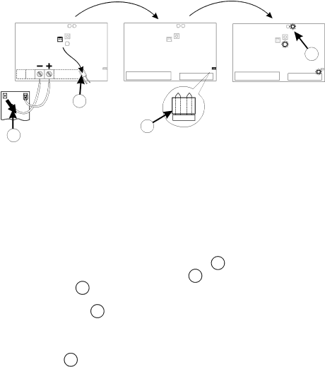
SELECTING PROGRAMME MODE

STEP 1 - Remove power from control card:

-for A5 remove electronics power only 69

-for D3/D5 remove battery power 70 as well as electronics power 69 .

STEP 2 - Fit “SET” link 71 .

STEP 3 - Reapply power (reversal of STEP 1). STATUS LED will flash 5 times on power up. Check that LED L2 and “SET” are ON.

LED L2 72 indicates controller is in “programme mode”.

21

Image 23
Contents Sliding Gate Automation Page Major Components Typical D5 Shown Oil Specifications Grade 75W90 Qty 75mlStart kgF RUN kgF Gate Mass kg 300 500 ANTI-LIFT Brackets Duty Cycle Curves Recommended Installation and Cable Thickness REQUIREMENTS† Option 1 Bolt down onto concrete plinth Mechanical Mounting DetailsPage Option 2 Set into concrete plinth Provision for Cables Gearbox Mounting Down Details Useful TIP Mounting Rack200mm Installing Chain Drive Systems Ensure fan has stopped turning Setting Mechanical Clutch A5 onlyMounting of Gate Sensor Mounting Configuration For Steel RackRemovable Connectors Power Wiring see page 15 for Signal WiringSignal Wiring CP80 and CP81 Recommended Lightning Protection Commissioning Block Diagram Gate Closes Towards Left Above Black Blue RED Towards Right Setting Motor DirectionSelecting Programme Mode A5 only Setting Gate LimitsStart Automated Gate Limits Routine Setting Gate LimitsD3/D5 Motor Automatic SET-UP Start Manual Gate Limits Routine Exit Gate Limits Routine D3/D5 onlyA5 Motor Manual SET-UP Align Origin SwitchFunctions Select Exit Gate Limits Routine A5 onlyFactory Defaults Highlighted Timer and Counter Setting Main Unit Menu Measure Fault Finders Guide D3 / D5 Operators Procedure to Programme Controller Back to Factory SettingsGate Opens to Pedestrian and Closes Page Centurion