SURFACE FINISHING WITH SANDING FLAP DISCS
1.Allow the tool to reach full speed before touching the tool to the work surface.
2.Apply minimum pressure to work surface, allowing the tool to operate at high speed. Sanding rate is greatest when the tool operates at high speed.
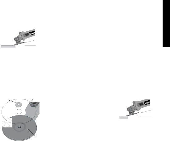
3.Maintain a 5˚ to 10˚ angle between ![]()
the tool and work surface.
4. Continuously move the tool in a |
| |
forward and back motion to avoid | ||
creating gouges in the work surface. | ||
|
5.Remove the tool from work surface
before turning tool off. Allow the tool to stop rotating before lay- ing it down.
MOUNTING SANDING BACKING PADS
![]() CAUTION: Turn off and unplug the tool before making any adjustments or removing or installing attachments or acces- sories. Before reconnecting the tool, turn the switch on and off as previously described to ensure that the tool is off.
CAUTION: Turn off and unplug the tool before making any adjustments or removing or installing attachments or acces- sories. Before reconnecting the tool, turn the switch on and off as previously described to ensure that the tool is off.
![]() CAUTION: Proper guard must be reinstalled for grinding wheel, sanding flap disc, wire brush or wire wheel applications after sand-
CAUTION: Proper guard must be reinstalled for grinding wheel, sanding flap disc, wire brush or wire wheel applications after sand-
ing applications are complete. |
|
| |
1. | Place or appropriately thread backing | H | S |
| pad (R) on the spindle. |
| |
|
|
| |
2. | Place the sanding disc (S) on the |
|
|
| backing pad. |
|
|
3.While depressing spindle lock, thread clamp nut (H) on spindle,
piloting the raised hub on the clamp nut into the center of sanding disc and backing pad.
R
4.Tighten the clamp nut by hand. Then depress the spindle lock button while turning the sanding disc until the sanding disc and clamp nut are snug.
5.To remove the wheel, grasp and turn the backing pad and sanding pad while depressing the spindle lock button.
USING SANDING BACKING PADS
Choose the proper grit sandpaper for your application. Sandpaper is available in various grits. Coarse grits yield faster material removal rates and a rougher finish. Finer grits yield slower material removal and a smoother finish.
Begin with coarse grit discs for fast, rough material removal. Move to a medium grit paper and finish with a fine grit disc for optimal finish.
Coarse | 16 - 30 grit |
Medium | 36 - 80 grit |
Fine Finishing | 100 - 120 grit |
Very Fine Finishing | 150 - 180 grit |
1.Allow the tool to reach full speed before touching tool to the work surface.
2.Apply minimum pressure to work surface, allowing the tool to operate at high speed. Sanding rate is greatest when the tool operates at high speed.
3.Maintain a 5˚ to 15˚ angle between
the tool and work surface. The sanding disc should contact approximately one inch of work surface.
4.Move the tool constantly in a straight5˚-15˚line to prevent burning and swirling of ![]() work surface. Allowing the tool to rest on the work surface with- out moving, or moving the tool in a circular motion causes burn- ing and swirling marks on the work surface.
work surface. Allowing the tool to rest on the work surface with- out moving, or moving the tool in a circular motion causes burn- ing and swirling marks on the work surface.
English
12