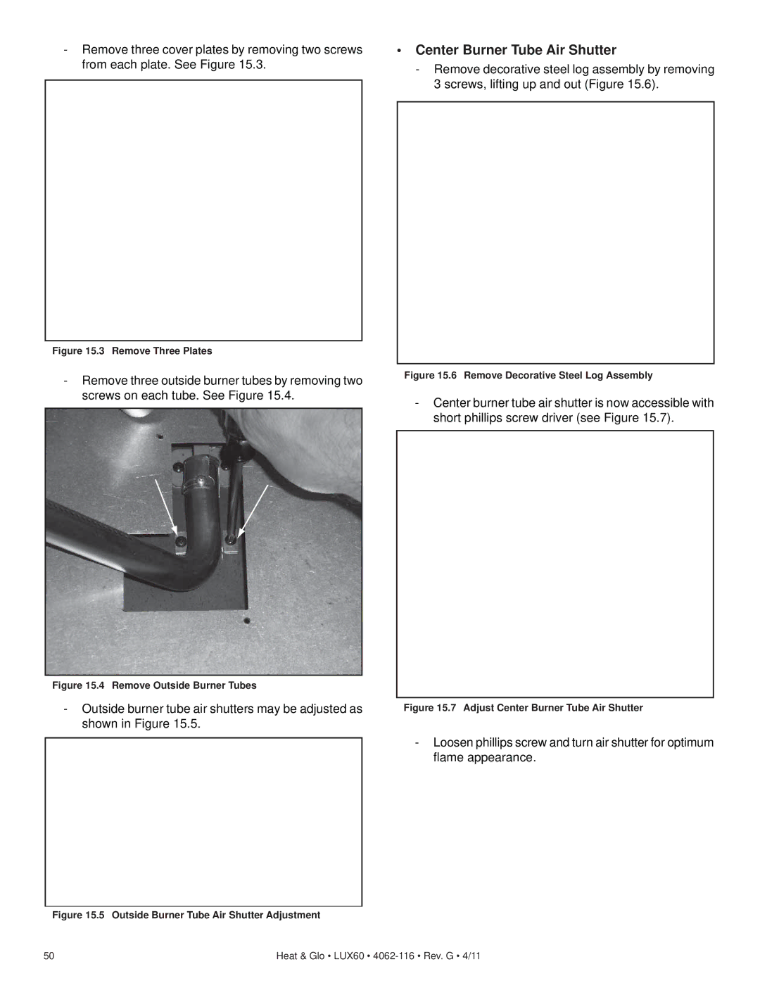
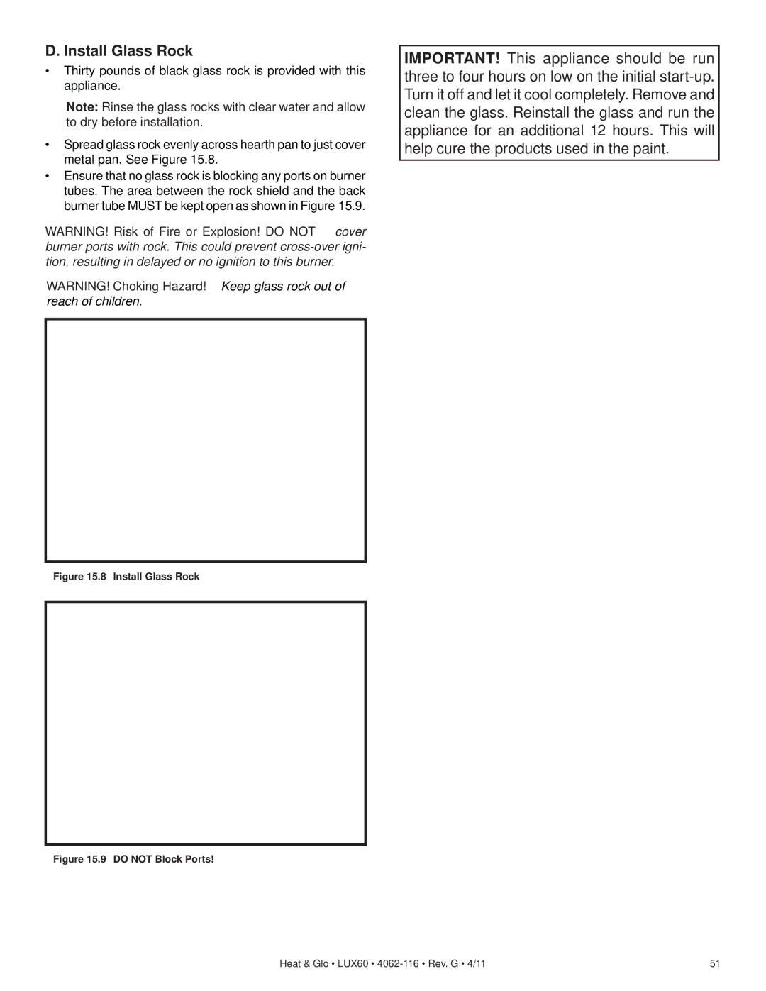
Heat & Glo LifeStyle LUX60 Appliance Setup, Remove Glass Assembly, Clean the Appliance

Page 49

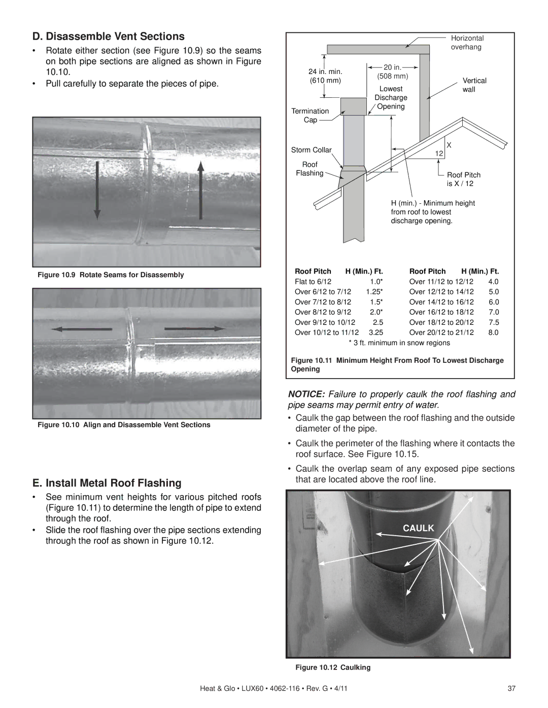
15 Appliance Setup

WARNING! Risk of Fire and Electric Shock! Use ONLY Hearth & Home Technologies-approved optional acces- sories with this appliance. Using non-listed accessories could result in a safety hazard and will void the warranty.

A. Remove Glass Assembly

WARNING! Risk of Asphyxiation! Handle fixed glass assembly with care. Inspect the gasket to ensure it is undamaged and inspect the glass for cracks, chips or scratches.

DO NOT strike, slam or scratch glass.

DO NOT operate fireplace with glass removed, cracked, broken or scratched.

Replace as a complete assembly.

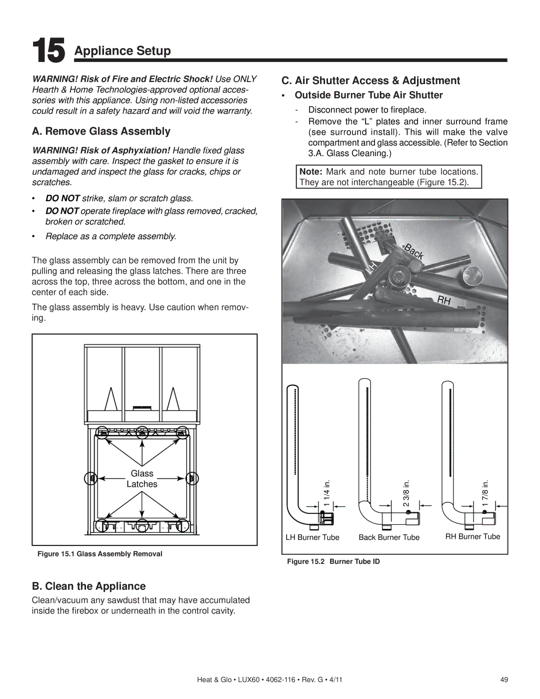
The glass assembly can be removed from the unit by pulling and releasing the glass latches. There are three across the top, three across the bottom, and one in the center of each side.

The glass assembly is heavy. Use caution when remov- ing.

Glass

Latches

Figure 15.1 Glass Assembly Removal

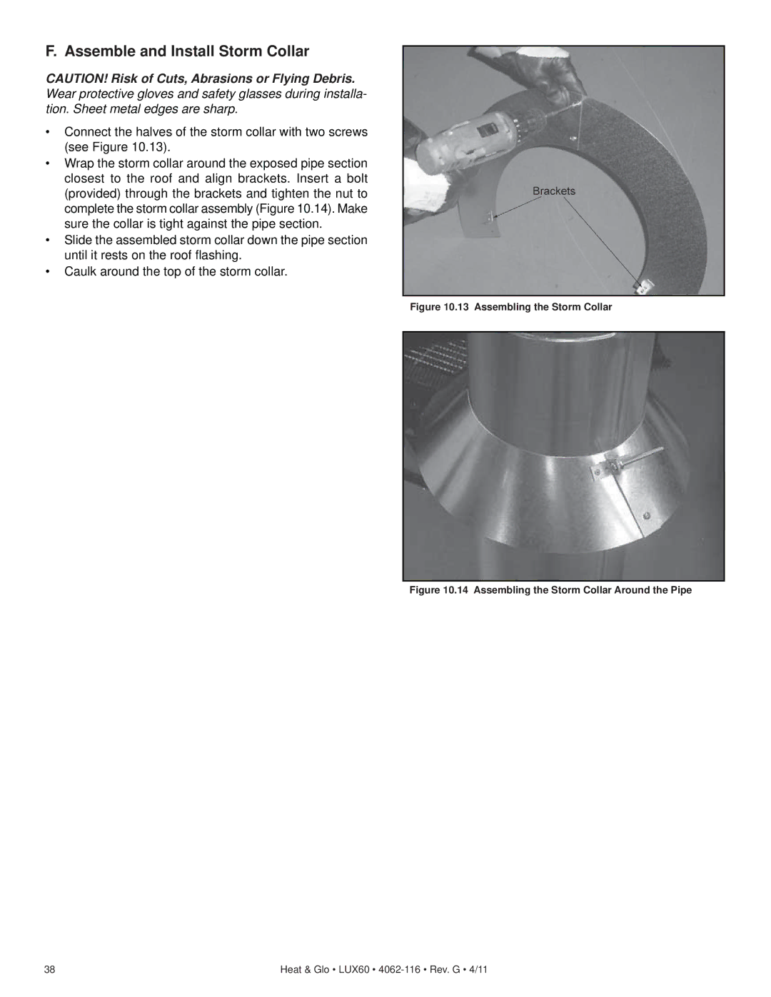
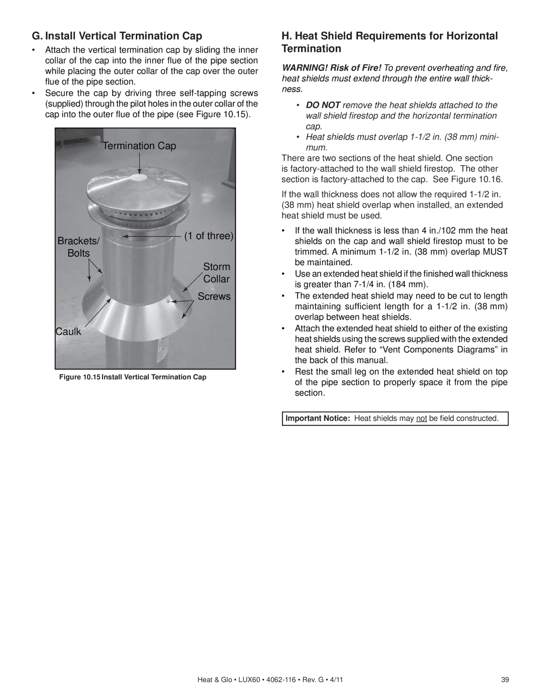
C. Air Shutter Access & Adjustment

Outside Burner Tube Air Shutter

-Disconnect power to fireplace.

-Remove the “L” plates and inner surround frame (see surround install). This will make the valve compartment and glass accessible. (Refer to Section 3.A. Glass Cleaning.)

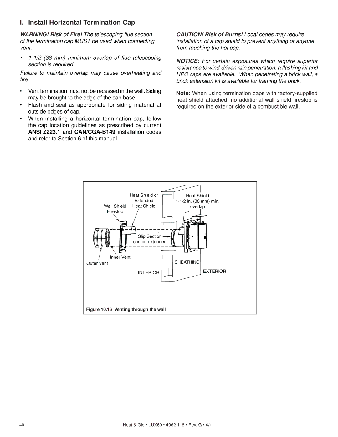
Note: Mark and note burner tube locations. They are not interchangeable (Figure 15.2).


Back


LH


RH

1 1/4 in.

2 3/8 in.

1 7/8 in.

LH Burner Tube

Back Burner Tube

RH Burner Tube

Figure 15.2 Burner Tube ID

B. Clean the Appliance

Clean/vacuum any sawdust that may have accumulated inside the firebox or underneath in the control cavity.

Heat & Glo • LUX60 • 4062-116 • Rev. G • 4/11

49

Image 49
Contents Models Installation and OperationHomeowner Reference Information CongratulationsTable of Contents Reference Materials Limited Lifetime Warranty  B. Limited Lifetime WarrantyWarranty Conditions Listing and Code Approvals Requirements for the Commonwealth of Massachusetts Operating Instructions Gas Fireplace SafetyYour Fireplace Clear Space Fixed Glass AssemblyDecorative Doors and Fronts Operation of the LUX60Matching Security Codes Before Lighting FireplaceSystem Operation IntelliFire Ignition System IPI Lighting Instructions For Your Safety Read Before LightingInitial Break-in Procedure Frequently Asked QuestionsAfter Fireplace is Lit Maintenance Tasks-Homeowner Maintenance and ServiceGlass Cleaning Doors, Surrounds, Fronts Remote ControlVenting Gasket Seal and Glass Assembly Inspection Maintenance Tasks-Qualified Service TechnicianFirebox Control Compartment and Firebox TopLED Light Bar Replacement Light Glass Replacement/CleaningBack Clean Porcelain PanelsRemove Screws Typical Appliance System Getting StartedTools and Supplies Needed Design and Installation ConsiderationsInspect Appliance and Components Select Appliance Location Framing and ClearancesAssemble Steel Stud Kit Clearances Construct the Appliance ChaseClearances to Combustibles Vent Termination Minimum Clearances Termination LocationsMinimum Clearances for Termination Approved Pipe Vent Information and DiagramsVent Table Key Use of ElbowsTop Vent Horizontal Termination Vent DiagramsOne Elbow Three Elbows Two 45 Elbows replacing One 90 ElbowNo Elbow Top Vent Vertical TerminationTwo Elbows Pipe Clearances to Combustibles Vent Clearances and FramingWall Penetration Framing Combustible Wall PenetrationCeiling firestop Must be used between floors and at- tics Install the Ceiling FirestopFlat Ceiling Installation Install Attic Insulation ShieldVaulted Ceiling Installation Secure and Level the Appliance Appliance PreparationAttach Pipe to the Firebox Assembly Install Vent PipeAssemble Vent Sections Assemble Pipe SectionsSecure the Vent Sections Assemble Slip SectionsDisassemble Vent Sections Install Metal Roof Flashing13 Assembling the Storm Collar Assemble and Install Storm CollarHeat Shield Requirements for Horizontal Termination Install Vertical Termination Cap16 Venting through the wall Install Horizontal Termination CapHHT Shrouds ShroudsField Constructed Shrouds Open Top Shroud may be used with DVP-TV, DVP-TVHWRoofed Style Shroud may be used with DVP-TV, DVP-TVHW Mailbox Style Shroud may be used with DVP-TV, DVP-TVHWGas Pressure Gas InformationGas Connection Setting Flame Height/Manifold Pressure Install Flame SolenoidElectrical Service and Repair Wiring RequirementsElectrical Information Junction Box Detail Junction Box InstallationStandard 1/2 in mm Sheetrock Wall FinishingAdditional Decorative Finishing over 1 in mm Thick Additional Decorative Finishing up to 1 in mm ThickRemove Glass Assembly Appliance SetupAir Shutter Access & Adjustment Clean the ApplianceCenter Burner Tube Air Shutter Outside Burner Tube Air Shutter AdjustmentInstall Glass Rock Install Glass RockIntelliFire IPI Ignition System TroubleshootingIntelliFire IPI Ignition System Reference Materials Appliance Dimension DiagramDVP45 Vent Components DiagramsDVP-TRAPFL DVP-TVHW DVP-TRAP Optional Components Do not Discard this Manual Contact Information