13.Inspect vertical and horizontal shafts for grooves, nicks, or bumps in the areas where the seals seat. Resurface any damage with emery cloth.
14.Inspect housing and caps for cracks or other damage.
Assemble Gearbox (Figure 15)
1.Clean housing, paying specific attention to areas where gaskets will be installed.
2.Wash housing and all components thoroughly. Select a clean area for gearbox assembly. Replace all seals, bearings, and gaskets. All parts must be clean and lightly oiled before reassembling.
3.Press bearing (18) in left side of gearbox housing using a round tube of the same diameter and a handpress.
4.Place gear (19) inside of gearbox housing.
5.Insert output shaft (14) through opening in right side of gearbox, gear (19), and bearing (18) on left side of housing.
6.Place second bearing (18) over output shaft on right side and press into housing, using a round tube of the same diameter and a handpress.
7.Install shim (17) and snap ring (16) to right side of housing to secure output shaft in housing.
8.Place seal (15) over output shaft on right side and press into housing, using a round tube of the same diameter and a handpress.
9.Install shim (17) and snap ring to left side of housing.
10.Place seal (15) over output shaft on left side and press into housing, using a round tube of the same diameter and a handpress.
11.Press bearings (11) into input housing (12), using a round tube of the same diameter and a handpress.
12.Assembly bearing (13), shim (17), gear (8), shim (7), and castle nut (6) to input shaft (1).
13.Align groove in castle nut (6) and hole in end of shaft and insert cotter pin (5).
14.Insert input shaft assembly into gearbox housing and align teeth of the two gears.
15.Place input housing (12) over input shaft (1) and secure into position using cap screws (10).
16.Place seal (2) over input shaft on cover and press into housing, using a round tube of the same diameter and a handpress.
17.Check gearbox housing for leaks by plugging all holes except one. Apply 4 psi compressed air and immerse the gearbox in water to verify that there are no leaks.
18.Remove gearbox from water and dry off with compressed air. Add SAE 80W or 90W EP oil until it runs out of level hole in front cover. Tighten all plugs.
Reinstall Gearbox
NOTE: Gearbox is heavy: do not attempt to move without mechanical assistance.
1.Install flex coupler driveline between side gearboxes and center gearbox.
2.Set gearbox on cutter and fasten with bolts and nuts. Torque bolts to 300
SIDE DRIVE SERVICE
|
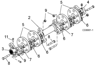
| 5. | Rubber disk |
|
| 6. | Shaped washer |
|
| 7. | Bushing |
2. | Shaft | 8. | Bolt |
3. | Inner yoke | 9. | Lock nut |
4. | Outer yoke | 11. | Set screw |
|
|
|
|
Figure 16. Side Drive Assembly
The drives between the center and side gearboxes contain rubber shock-absorbing discs. To service or remove the side drives or remove a gearbox, the flexible coupling must be disassembled. See page 25 for rubber disk replacement.
Remove end yokes by removing nuts (9) and sliding bolt (8) inward to clear yoke. Do not remove bolt unless rubber disks (5) are to be serviced. Remove complete center section by lifting straight up on center shaft (2). The outer yoke can be slid off gearbox shaft. The inner yoke is held by two set screws (11).
Reassemble shaft as shown in Figure 16. End yokes (3
&4) do not bolt directly to center shaft (2). Use the special formed washer (6) and bushings (7) between the rubber disks (5) and under bolt head or nut near rubber disc. Tighten nuts (9) and bolts (8) to 85 lbs-ft. Tighten set screw (11).
NOTE: Crossbar must be
MAN0571 (Rev. 6/15/2007) | Dealer Service 33 |
|
|