- INSTALLATION MANUAL -
INSTALLATION
INTRODUCTION
After unpacking the appliance make sure it has not been damaged. (pict.21)
Make sure the supply wiring comply with the ratings (i.e., V, kW, Hz, no. of phases and main power). Check and record the coolant type inside the refrigeration system and refer to this recorded data upon any refrigerant refill.
Pict.21
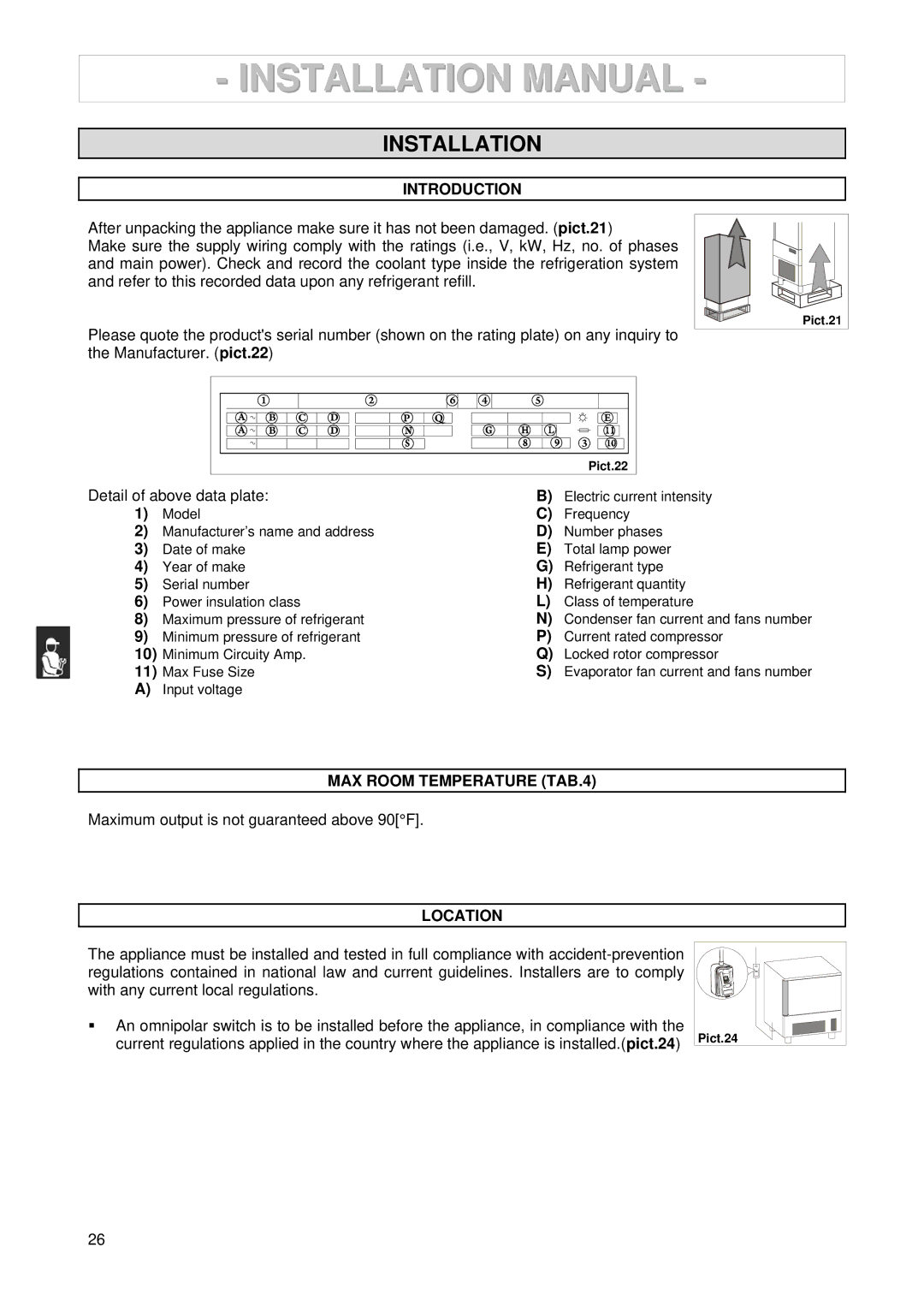
Please quote the product's serial number (shown on the rating plate) on any inquiry to the Manufacturer. (pict.22)
| 1 |
| 2 |
| 6 | 4 | 5 |
A | B | C | D | P | Q |
| E |
A | B | C | D |
|
|
| 3 |
|
|
|
|
|
|
| |
|
|
|
|
|
|
| Pict.22 |
Detail of above data plate: | B) | Electric current intensity | |
1) | Model | C) | Frequency |
2) | Manufacturer’s name and address | D) | Number phases |
3) | Date of make | E) | Total lamp power |
4) | Year of make | G) | Refrigerant type |
5) | Serial number | H) | Refrigerant quantity |
6) | Power insulation class | L) | Class of temperature |
8) | Maximum pressure of refrigerant | N) | Condenser fan current and fans number |
9) | Minimum pressure of refrigerant | P) | Current rated compressor |
10) | Minimum Circuity Amp. | Q) | Locked rotor compressor |
11) | Max Fuse Size | S) | Evaporator fan current and fans number |
A)Input voltage
MAX ROOM TEMPERATURE (TAB.4)
Maximum output is not guaranteed above 90[°F].
LOCATION
The appliance must be installed and tested in full compliance with
An omnipolar switch is to be installed before the appliance, in compliance with the current regulations applied in the country where the appliance is installed.(pict.24) Pict.24
26