Manuals
/
3Com
/
Computer Equipment
/
Switch
3Com
5124M-TPCL
manual
Shows the location of the LEDs on Model Number 5124M-TP
Models:
5124M-TP
5124M-TPCL
1
72
102
102
Download
102 pages
41.67 Kb
69
70
71
72
73
74
75
76
Troubleshooting
Specification
Install
Default
Connecting Twisted Pair Cables
Star-Wiring Configuration
Accessing the 3Com MIB
Using 90 Cable Connectors
Unpacking Procedures
Setting Port Redundancy
Page 72
Image 72
Figure
3-8
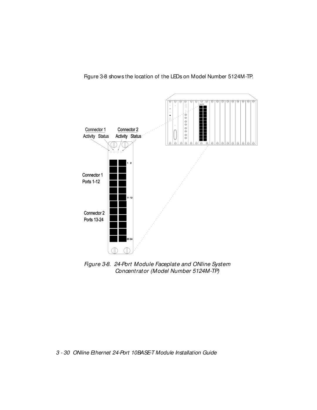
shows the location of the LEDs on Model Number
5124M-TP.
Figure
3-8.
24-Port
Module Faceplate and ONline System Concentrator (Model Number
5124M-TP)
3 - 30 ONline Ethernet
24-Port
10BASE-T
Module Installation Guide
Page 71
Page 73
Page 72
Image 72
Page 71
Page 73
Contents
ONline Ethernet 24-Port 10BASE-T Module Installation Guide
VDE Class B Compliance
Restricted Rights
Page
Contents
Installing and Operating the Module
Troubleshooting
Page
Figures
ONline Ethernet 24-Port 10BASE-T Module Installation Guide
Tables
Page
How to Use This Guide
Audience
Structure of This Guide
Document Conventions
Convention Indicates Example
Usr/snm/agents
Related Documents
3Com Documents
Reference Documents
Page
Introduction
Ethernet 24-Port 10BASE-T Module Description
Module Features
Model Number 5124M-TPCL Features
Bank Switching Capability
Model Number 5124M-TP Features
Theory of Operation
Typical 24-Port Module Configuration
Page
Designing and Expanding the Network
Rules for Configuring a Network
Understanding the General Rules
Seven Basic Network Rules
Rule Definition Recommendations/Notes
Certain LAN devices
Seven Basic Network Rules
LAN Equivalence
LAN Product Equivalent Distances
LAN Product Equivalent Distance meters
Choosing a Network Backbone Cabling Structure
LAN Product Equivalent
Building a Network Star Configuration
Star-Wiring Configuration
Building a Network Serial Configuration
Serial Configuration
Port Module Configurations
Fiber Backbone, 10BASE-T To-The-Desk
Example Sample Configuration Distance Calculation
10BASE-T Backbone, 10BASE-T To-The-Desk
Unshielded Twisted Pair Network Using 24-Port Modules
Using Patch Panels
Establishing Fault-Tolerant Configurations
Setting Port Redundancy
Setting Backbone Redundancy
Redundant Twisted Pair Backbone
Designing and Expanding the Network 2
Page
Installing and Operating the Module
Precautionary Procedures
Quick Installation
Procedures for Completing Installation
Step Procedure Section Title
Establish connections from the 24-Port
Unpacking Procedures
Setting the DIP Switches
DIP Switch Overview
Model 5124M-TPCL and Model 5124M-TP DIP Switch Location
DIP Switch Description
DIP Switch Settings
Label Function Factory DIP Switch Setting
Default
Channel Network Select DIP Switch Settings
DIP Switch Setting Conn
Network Selection
Installing the Module
Installing a 24-Port Module Model Number 5124M-TPCL
Port Module Cable Connection Model Number 5124M-TPCL
Using 90 Cable Connectors
Installing the Cable Tie-Wrap Kit
Attaching the Tie-Wrap Bracket to the Module
Securing 90 Cables to the Module
Attaching Cables With 90 Connectors
Configuration in a Managed Environment
If Management is Not Available
Before Configuring the Module
Enabling Ports
Enabling Port Redundancy
Enabling Link Integrity
Selecting a Network
Enabling Remote Diagnostics Mode
Setting the Autopartition Threshold Value
Saving Module Configurations
Showing Module Configurations
Show Module
Show Port
Telco
Gathering Network Statistics
Selecting the Per-Port Counters Connector
Monitoring the Front Panel
Shows the location of the LEDs on Model Number 5124M-TPCL
Shows the location of the LEDs on Model Number 5124M-TP
Port Module LED Interpretations
LED Name Color State Indicates
Using the LED Check Button
Verifying LED and Network Assignments
LED State Network Configuration
Network Check Codes
Page
Troubleshooting
Troubleshooting Using the Port Status LEDs
Troubleshooting Using the Port Status LEDs
LED State Indication Possible Cause Corrective Action
Troubleshooting Using the Port Status LEDs
Troubleshooting Using the Port Activity LEDs
Troubleshooting Using the Port Activity LEDs
Technical Assistance
LED State Possible Cause Corrective Action
Specifications
General Specifications
Table A-1 -Port Module General Specifications
Specification Value
Model Number 5124M-TP
Power Specifications
Table A-2 -Port Module Power Specifications
Power Specifications Values
Environmental Specifications
Table A-3 -Port Module Fuse Specifications
Fuse Specifications for 24-Port Module
Table A-4 -Port Module Environmental Specifications
Mechanical Specifications
Twisted Pair Cable and Connector Specifications
Table A-5 -Port Module Mechanical Specifications
Mechanical 5124M-TPCL Values 5124M-TP Values Specifications
Twisted Pair Cable Specifications
Table A-6. IBM Twisted Pair Cable Specifications
IBM Type No.
Shielding Nominal Pairs Impedance
Twisted Pair Connector Specifications
RJ-45 Connector Pinouts
Pin Connector Pinouts
Figure A-1 -Port Module RJ-45 Connector Pinouts
Figure A-2 -Pin Male and Female Connectors
Table A-7 -Pin Cable Pinouts and Port Assignments
Port TX, + RX, + Not Used
Connecting Twisted Pair Cables
Technical Support
On-line Technical Support
Support from Your Network Supplier
Email Technical Support
World Wide Web Site
Support from 3Com
Accessing the 3Com MIB
Returning Products for Repair
3Com Technical Publications
Page
Index
Activity LEDs, 3-29,3-31
VDE compliance
Top
Page
Image
Contents