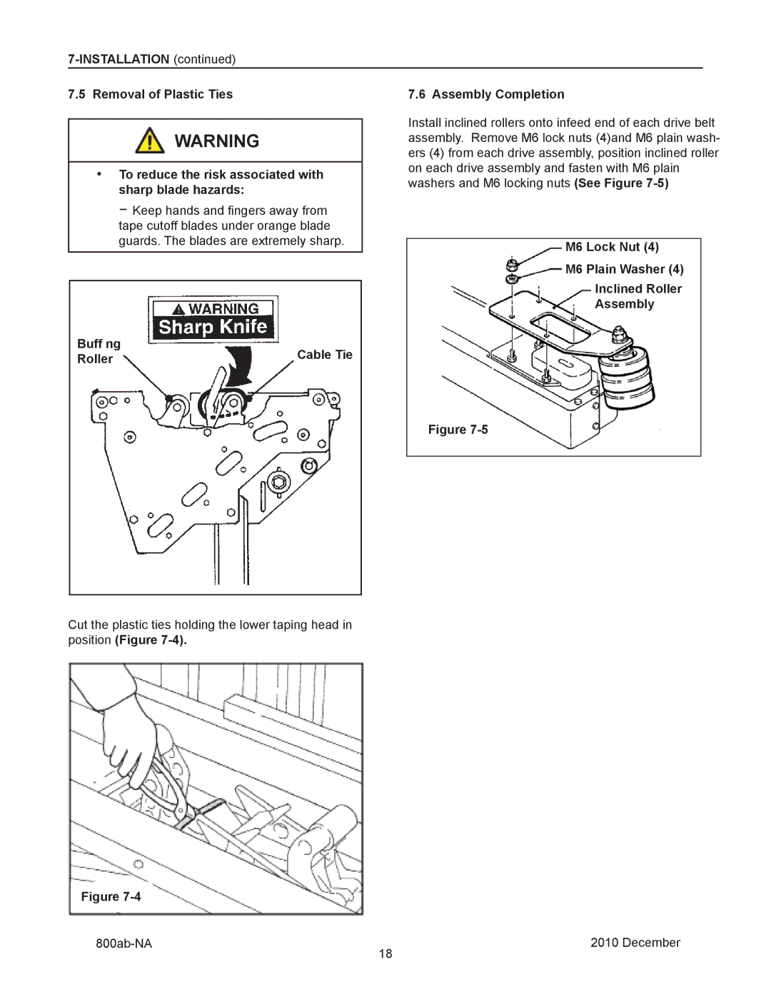
7.5 Removal of Plastic Ties | 7.6 Assembly Completion | |||
|
|
| Install inclined rollers onto infeed end of each drive belt | |
|
| WARNING | ||
|
| |||
|
| assembly. Remove M6 lock nuts (4)and M6 plain wash- | ||
|
|
| ers (4) from each drive assembly, position inclined roller | |
|
|
| ||
|
|
| on each drive assembly and fasten with M6 plain | |
• To reduce the risk associated with | ||||
washers and M6 locking nuts (See Figure | ||||
sharp blade hazards: | ||||
| ||||
−Keep hands and fingers away from tape cutoff blades under orange blade
guards. The blades are extremely sharp. | M6 Lock Nut (4) |
|
M6 Plain Washer (4)
Inclined Roller
Assembly
Buff ng | Cable Tie |
Roller |
Figure
Cut the plastic ties holding the lower taping head in position (Figure
Figure |
|
| 2010 December |
| 18 |