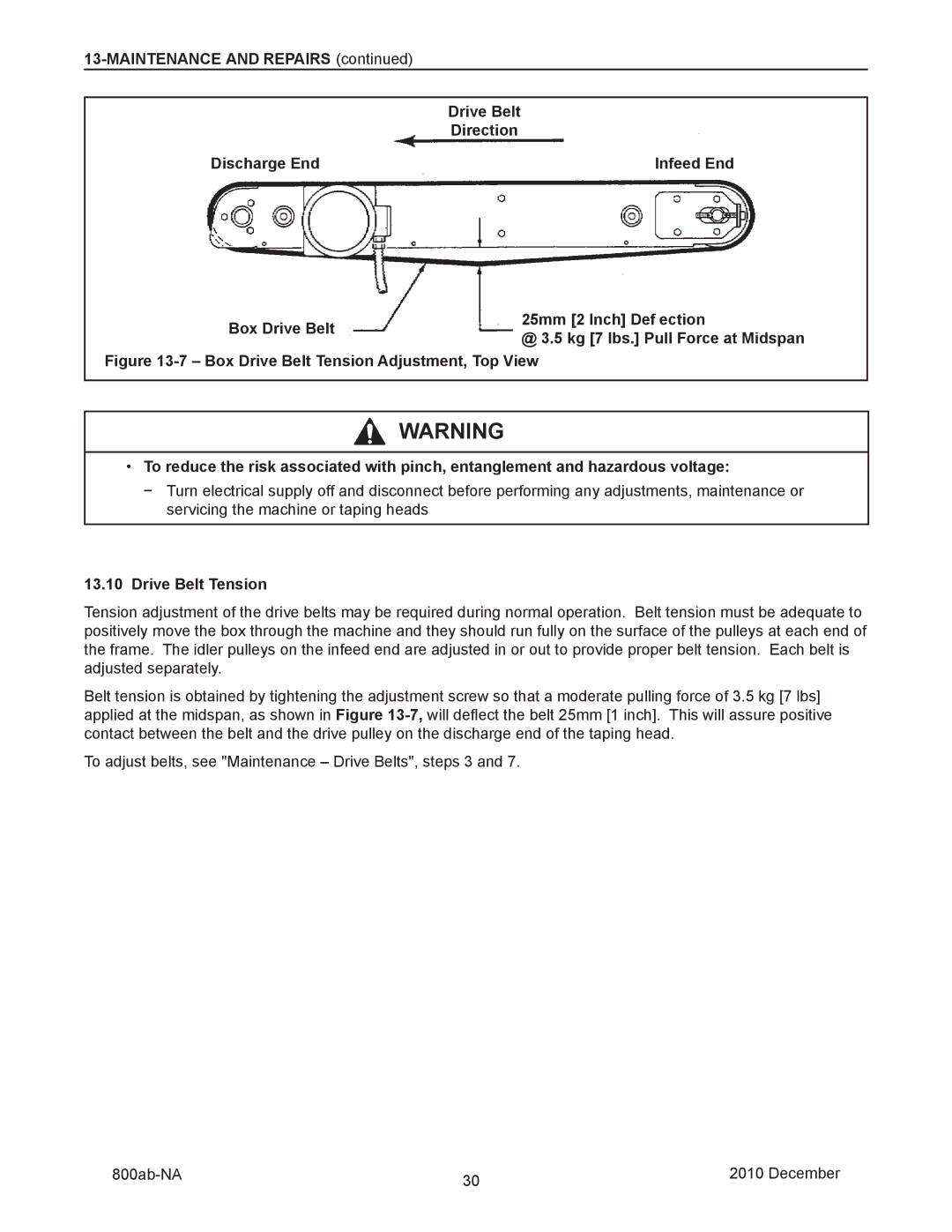
Drive Belt
Direction
Discharge End |
| Infeed End |
|
|
|
|
| 25mm [2 Inch] Def ection | |
Box Drive Belt | |||
| @ 3.5 kg [7 lbs.] Pull Force at Midspan | ||
|
| ||
|
|
|
Figure 13-7 – Box Drive Belt Tension Adjustment, Top View
![]() WARNING
WARNING
•To reduce the risk associated with pinch, entanglement and hazardous voltage:
−Turn electrical supply off and disconnect before performing any adjustments, maintenance or servicing the machine or taping heads
13.10Drive Belt Tension
Tension adjustment of the drive belts may be required during normal operation. Belt tension must be adequate to positively move the box through the machine and they should run fully on the surface of the pulleys at each end of the frame. The idler pulleys on the infeed end are adjusted in or out to provide proper belt tension. Each belt is adjusted separately.
Belt tension is obtained by tightening the adjustment screw so that a moderate pulling force of 3.5 kg [7 lbs] applied at the midspan, as shown in Figure
To adjust belts, see "Maintenance – Drive Belts", steps 3 and 7.
30 | 2010 December | |
|
|