Manuals
/
3M
/
Computer Equipment
/
Tablet Accessory
3M
800ab
manual
Dimensional Drawing
Models:
800ab
1
89
122
122
Download
122 pages
34.01 Kb
86
87
88
89
90
91
92
93
Specifications
Install
Technical Diagrams
Dimension
Maintenance
Options and Accessories
SET UP and Adjustments
Box Drive Assembly, Infeed End
Tape Width Adjustment
Inspection of Phases
Page 89
Image 89
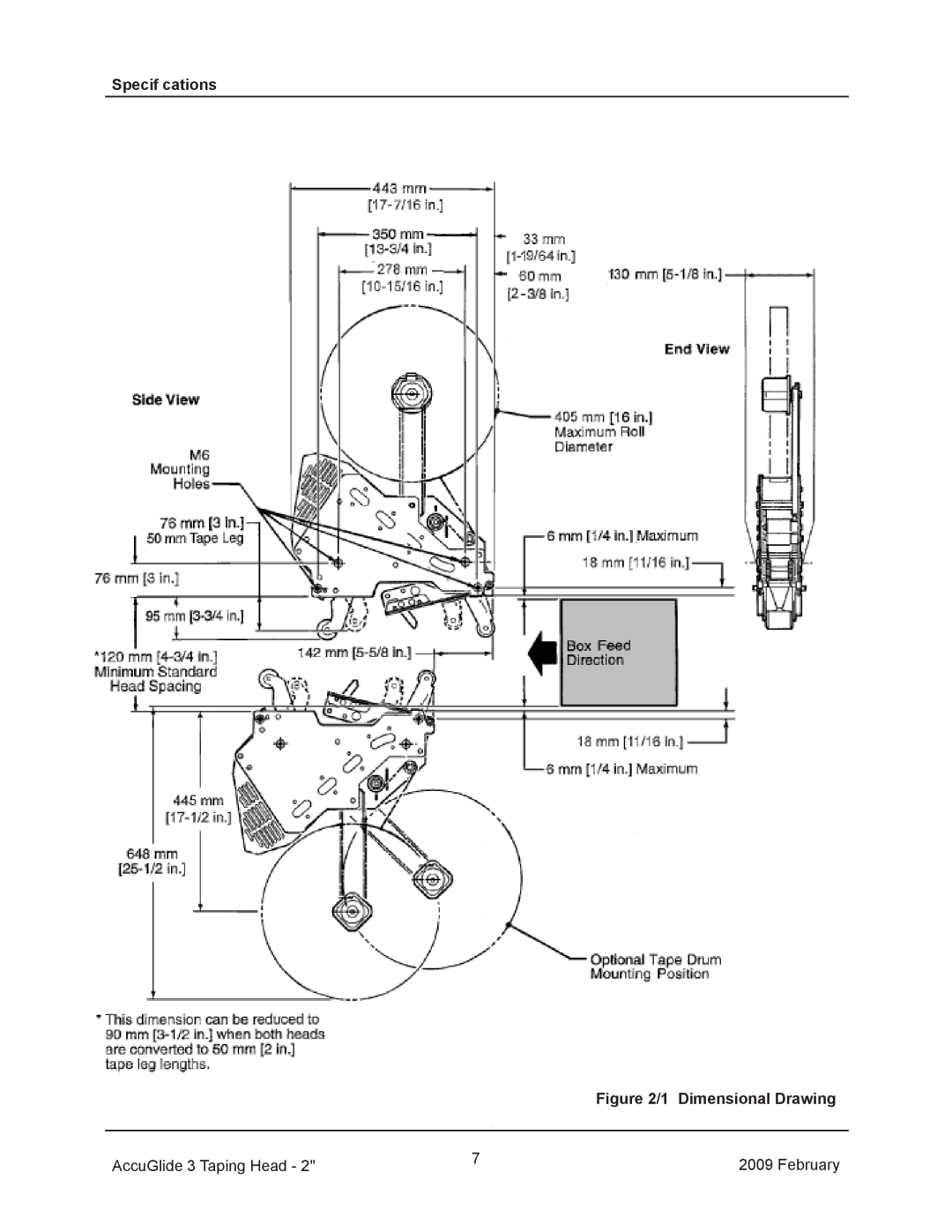
Specif cations
Figure 2/1 Dimensional Drawing
AccuGlide 3 Taping Head - 2"
7
2009 February
Page 88
Page 90
Page 89
Image 89
Page 88
Page 90
Contents
3M 2010 44-0009-2082-5 B121510-NA
Industrial Adhesives and Tapes
3M-MaticTM800ab-NAAdjustable case sealer
3M Center, Building 220-5E-06 St. Paul, MN
This page is Blank
3M 2010 44-0009-1852-2 F031008-NA
This page is Blank
General Information
Safety
Introduction
This page is Blank
Installation
Table of Contents Shipment, Handling, and Storage
Safety devices
Set-Up and Adjustments
This page is Blank
Maintenance
Table of Contents Operation
Additional Instructions
Technical Documentation and Information
Abbreviations and Acronyms List of ABBREVIATIONS, Acronyms
Manufacturing Specif cations / Description / Intended Use
3M-MaticTM800ab Adjustable Case Sealer, Type
Introduction
Consulting the Manual
Manual Maintenance
Importance of the Manual
General Information
Contents-800ab Adjustable Case Sealer
Stop Switch
Safety
General Safety Information
To reduce the risk associated with hazardous voltage
To reduce the risk associated with pinches hazards
To reduce the risk associated with sharp blade hazards
To reduce the risk associated with muscle strain
Operators Qualif cations
Personal Safety Measures
See Section Number of Operators
Instructions for a Safe Use of the Machine
Skill 1 Machine Operator
800ab Case Sealer Components Left Front View
Component Locations
Safety
Power Requirements
Specifications
Operating Rate
Operating Conditions
Box Weight and Size Capacities
Specifications Specif cations Tape Roll Diameter
Tape Application Leg Length Standard
Tape Application Leg Length Optional
Set-Up Recommendations
Packaging for Overseas Shipment Optional Figure
SHIPMENT-HANDLING-STORAGE, Transport
Handling and Transportation of Uncrated Machine
Storage of the Packed or Unpacked Machine
Uncrating
Unpacking
Removal of Pallet
Disposal of Packaging Materials
M8 x 16mm Socket Head Screws Adjustable
Installation
Tool Kit Supplied with the Machine
Machine Set-Up / Bed Height
Roller
M6 Plain Washer Inclined Roller Assembly Buff ng
M6 Lock Nut
Preliminary Electric Inspection For Three-Main Phases Only
Inspection of Phases
Outboard Tape Roll Holder
Machine Connection to the Mains
Theory of Operation
Controls
Stop Switch Electric System / Circuit Breaker
Safety Devices of the Machine
Blade Guards
Emergency Stop Button
SET UP and Adjustments
Operation
Operation Troubleshooting Guide Problem Cause Correction
This page is Blank
Check Eff ciency of Safety Features
Maintenance and Repairs
Cleaning of Machine Qualif cation
Cleaning of Cutter Blade Qualif cation
Box Drive Belt Left Side View Infeed End
Drive Belt Replacement
Drive Pulley Rings Installation
Box Drive Assembly, Infeed End
Drive Belt Tension
Tape LEG Length
Reassemble Figure
Disassemble Figure
11C Master Link Mark Chain Sprocket
10 Crank/Chain Guards
This page is Blank
800ab-NA December
This page is Blank
Case of Fire
Additional Instructions Enclosures / Special Info
This page is Blank
Electric Diagram
Technical Diagrams
Label Kit
Machine Model Serial Number
Part Number Option/Accessory
Options and Accessories
This page is Blank
800ab-NA December
800ab
800ab 15407 Ref. No 3M Part No Description
800ab Front
800ab Ref. No 3M Part No Description
800ab Rear
800ab Ref. No 3M Part No Description
22 46 457 7
800ab 6174 Ref. No 3M Part No Description
Optional
800ab Ref. No 3M Part No Description
410
800ab Ref. No 3M Part No Description
800ab
800ab Ref. No 3M Part No Description
800ab
6176-8
800ab 6176 Ref. No 3M Part No Description
123
800ab Ref. No 3M Part No Description
This page is Blank
AccuGlideTM
Page
Replacement Parts and Service Information To Our Customers
This page is Blank
3M 2009 44-0009-1852-2 F031008
This page is Blank
Dimensional Drawing
AccuGlide 3 Taping Head February
AccuGlide 3 Upper Taping Head 2 inch, Type
Intended Use
This page is Blank
Updating the Manual
General Information How to use this Manual
To reduce the risk associated with mechanical hazards
Them Before Installing or Operating this Equipment
To reduce the risk associated with impact hazards
Upper Taping Head Label Lower Taping Head Label
Important Safeguards
Specif cations Tape
Taping Head Dimensions
Tape Width
Box Size Capacities
Dimensional Drawing
Tape Width Adjustment
Installation Guidelines
Receiving And Handling
To reduce risk associated with muscle strain
AccuGlide 3 Taping Head February
Operation on next
One-Way Tension Roller Wrap Knurled Applying
Tape Loading Upper Taping Head
Tape Loading Lower Taping Head
AccuGlide 3 Taping Head February
Blade Guard
Knife Holder Guard Blade Replacement
Hex Socket Section View 5mm HexRoller/Shaft Key Wrench
Applying/Buff ng Roller Replacement
Tape Drum Friction Brake Figure
Tape Latch Alignment Figure
One-Way Tension Roller
Applying Mechanism Spring
Changing Tape Leg Length
Leading Tape Leg Length Adjustment Figure
Page
Page
Qty Ref. No Part Number Description
Spare Parts/Service Information Recommended Spare Parts
Replacement Parts and Service
Page
10922
10923
Upper Head AccuGlide 3 Taping Head February
Upper Head Ref. No 3M Part No Description
Upper and Lower Heads
Upper and Lower Heads Ref. No 3M Part No Description
Upper Head
Upper Head Ref. No 3M Part No Description
Upper and Lower Heads AccuGlide 3 Taping Head August
Upper and Lower Heads Ref. No 3M Part No Description
AccuGlide 3 Taping Head August
Upper and Lower Heads Ref. No 3M Part No Description
Upper and Lower Heads AccuGlide 3 Taping Head February
Latch Upper and Lower Heads Ref. No 3M Part No Description
Lower Head AccuGlide 3 Taping Head February
Lower Head Ref. No 3M Part No Description
Lower Head
Lower Head Ref. No 3M Part No Description
This page is Blank
Top
Page
Image
Contents