![]() WARNING
WARNING
•To reduce the risk associated with pinch, entanglement and hazardous voltage:
−Turn electrical supply off and disconnect before performing any adjustments, maintenance or servicing the machine or taping heads
G
G
G
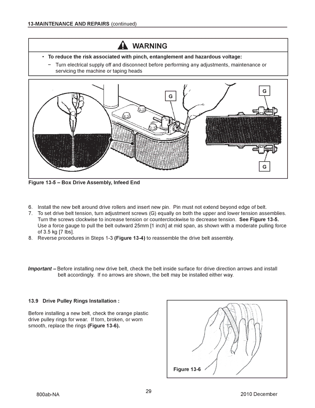
Figure 13-5 – Box Drive Assembly, Infeed End
6.Install the new belt around drive rollers and insert new pin. Pin must not extend beyond edge of belt.
7.To set drive belt tension, turn adjustment screws (G) equally on both the upper and lower tension assemblies. Turn the screws clockwise to increase tension or counterclockwise to decrease tension. See Figure
8.Reverse procedures in Steps
Important – Before installing new drive belt, check the belt inside surface for drive direction arrows and install belt accordingly. If no arrows are shown, the belt may be installed either way.
13.9 Drive Pulley Rings Installation :
Before installing a new belt, check the orange plastic drive pulley rings for wear. If torn, broken, or worn smooth, replace the rings (Figure
|
|
| Figure |
|
| 29 |
|
|
|
|
|
|
| |
|
| 2010 December | ||
|
|
|