|
|
|
| One Way |
|
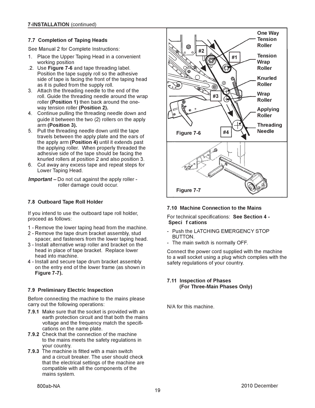
7.7 Completion of Taping Heads |
|
| Tension |
| |
See Manual 2 for Complete Instructions: | #2 |
| Roller |
| |
| Tension |
| |||
1. | Place the Upper Taping Head in a convenient | #1 |
| ||
|
| ||||
| working position |
|
| Wrap |
|
.2. Use Figure |
|
| Roller |
| |
| Position the tape supply roll so the adhesive |
|
| Knurled |
|
| side of tape is facing the front of the taping head |
|
|
| |
| as it is pulled from the supply roll. |
|
| Roller |
|
3. Attach the threading needle to the end of the |
| #3 | Wrap |
| |
| roll. Guide the threading needle around the wrap |
|
| ||
|
| Roller |
| ||
| roller (Position 1) then back around the one- |
|
|
| |
| way tension roller (Position 2). |
|
| Applying |
|
4. Continue pulling the threading needle down and |
|
| Roller |
| |
| guide it between the two (2) rollers on the apply |
|
|
| |
|
|
| Threading |
| |
| arm (Position 3). |
|
|
| |
5. Pull the threading needle down until the tape | Figure | #4 | Needle |
| |
| travels between the apply plate and the ears of |
|
|
|
|
| the apply arm (Position 4) until it extends past |
|
|
|
|
|
|
|
|
| |
| the applying roller. When properly threaded the |
|
|
|
|
| adhesive side of the tape should be facing the |
|
|
|
|
| knurled rollers at position 2 and also position 3. |
|
|
|
|
6.Cut away any excess tape and repeat steps for Lower Taping Head.
Important – Do not cut against the apply roller - roller damage could occur.
Figure
7.8 Outboard Tape Roll Holder
If you intend to use the outboard tape roll holder, | 7.10 Machine Connection to the Mains | ||
For technical specifications: See Section 4 - | |||
proceed as follows: | |||
Speci f cations | |||
1 - Remove the lower taping head from the machine. | |||
- Push the LATCHING EMERGENCY STOP | |||
2 - Remove the tape drum bracket assembly, stud | |||
BUTTON. | |||
spacer, and fasteners from the lower taping head. | |||
- The main switch is normally OFF. | |||
3 - Install alternative wrap roller and bracket on the | |||
head in place of tape bracket. Replace lower | Connect the power cord supplied with the machine | ||
head into machine. | to a wall socket using a plug which complies with the | ||
4 - Install and secure tape drum bracket assembly | safety regulations of your country. | ||
on the entry end of the lower frame (as shown in |
| ||
Figure |
| ||
|
| 7.11 Inspection of Phases | |
7.9 Preliminary Electric Inspection | (For | ||
| |||
Before connecting the machine to the mains please |
| ||
carry out the following operations: | N/A for this machine. | ||
7.9.1 | Make sure that the socket is provided with an | ||
| |||
| earth protection circuit and that both the mains |
| |
| voltage and the frequency match the specifi- |
| |
7.9.2 | cations on the name plate. |
| |
Check that the connection of the machine |
| ||
| to the mains meets the safety regulations in |
| |
7.9.3 | your country. |
| |
The machine is fitted with a main switch |
| ||
| and a circuit breaker. The user should check |
| |
| that the electrical settings of the machine are |
| |
| compatible with all the components of the |
| |
| mains system. |
| |
2010 December | |||
|
| 19 | |