Maintenance Flowchart
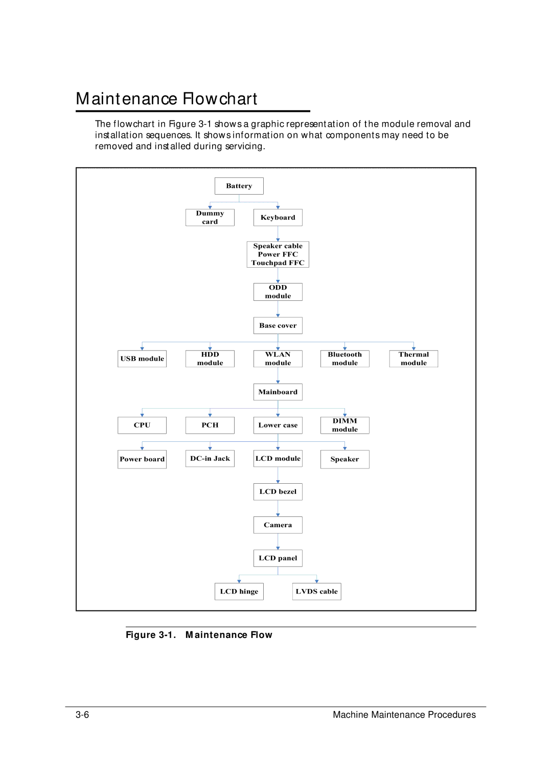
The flowchart in Figure
| Battery |
|
|
| |
| Dummy |
| Keyboard |
|
|
| card |
|
|
| |
|
|
|
|
| |
|
| Speaker cable |
|
| |
|
| Power FFC |
|
| |
|
| Touchpad FFC |
|
| |
|
|
| ODD |
|
|
|
|
| module |
|
|
|
|
| Base cover |
|
|
USB module | HDD |
| WLAN | Bluetooth | Thermal |
module |
| module | module | module | |
|
| ||||
|
| Mainboard |
|
| |
CPU | PCH | Lower case | DIMM |
| |
module |
| ||||
|
|
|
|
| |
Power board | LCD module | Speaker |
| ||
|
|
| LCD bezel |
|
|
|
|
| Camera |
|
|
|
|
| LCD panel |
|
|
| LCD hinge | LVDS cable |
| ||
Figure 3-1. Maintenance Flow
Machine Maintenance Procedures |