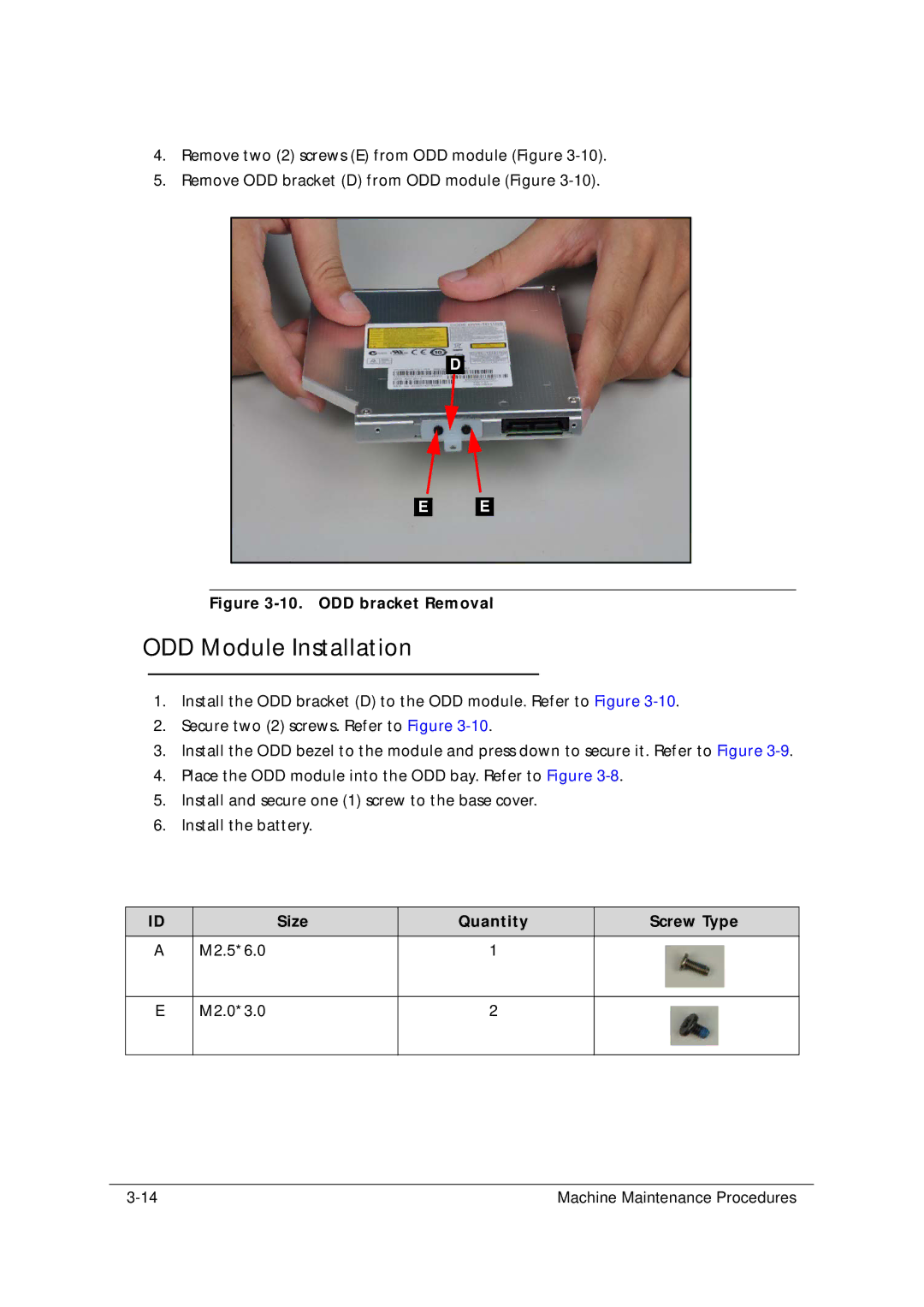
4.Remove two (2) screws (E) from ODD module (Figure
5.Remove ODD bracket (D) from ODD module (Figure
D |
E |
E |
Figure 3-10. ODD bracket Removal
ODD Module Installation
1.Install the ODD bracket (D) to the ODD module. Refer to Figure
2.Secure two (2) screws. Refer to Figure
3.Install the ODD bezel to the module and press down to secure it. Refer to Figure
4.Place the ODD module into the ODD bay. Refer to Figure
5.Install and secure one (1) screw to the base cover.
6.Install the battery.
ID | Size | Quantity | Screw Type |
|
|
|
|
A | M2.5*6.0 | 1 |
|
E
M2.0*3.0
2
Machine Maintenance Procedures |
